www.enersys.com Publication No. US-RE-IOM-002 January 2012 Page 1
1.0 GENERAL INFORMATION
1.1 Introduction
The EnerSys
®
range of PowerSafe
®
RE batteries has been designed for use in renewable
energy applications. PowerSafe RE cells are designed for applications where the battery must
undergo repeated cycling with daily depths of discharge (“DOD”) of up to 80% DOD (such as
rural settlements, communications systems and lighting systems, etc.). The RE range’s abilities
allow them to excel in highly demanding stored energy applications:
• Long cycle life
• Overcharge ability
• Cycling in state of discharge
• Low rate of self-discharge
• Large electrolyte reserve
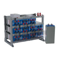
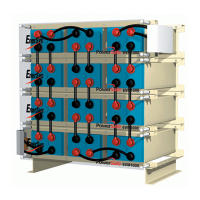
1.1.1 Cell Design
PowerSafe
RE cells are based on conventional, vented technology and designed for renewable
energy applications that require maximum cycle life with the highest level of reliability. They are
particularly suitable for use in solar energy installations, ensuring a continuity of electrical supply
during the hours of darkness or during periods of reduced sunshine. The entire RE range
utilizes tubular positive plates with EnerSys’ proprietery tube technology. Tubular positive plates
are widely used in batteries for particularly demanding applications. The current carrying lead
metal in tubular designs are entirely surrounded by active material – reducing the corrosion rate
and ensuring long life.
The RE range benefits from the square tubular plate when compared to both round tube and flat
plate battery designs. The PowerSafe RE battery’s square tubes provide more surface area on
the positive plate, exposing more positive plate active material to the electrolyte. The unique
tube construction also prevents shedding of the active material – a common failure mode in flat
plate designs that can lead to early failure due to sediment shorts. This combination of greater
positive surface area and reduced shedding allow for excellent cycling capacity.
Reduced maintenance is achieved through the use of additional electrolyte space above the
element, which means cells may only have to be watered every 6 months depending on
environmental conditions and duty cycle. Each cell is provided with a combination flame arrestor
and float level indicator which clearly indicates when the electrolyte level is low and water must
be added. The ample watering space and easily readable indicators help to reduce
maintenance costs and makes them an ideal solution for many remote or unmanned locations.
 Loading...