11
Checking the wear of the driver chuck and
hammer cylinder
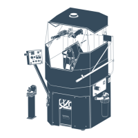
Wear to the driver chuck and hammer cylinder should be checked
regularly, e.g. every time the bit is reground or changed. Meas-
ure the diameter of the hammer cylinder using a sliding calliper.
Measure along the full length of the cylinder, with the exception
of the outermost 100 mm at each end. At any point between these
points, the diameter of the hammer cylinder must not be less than
the mini mum permissible diameter given for the respective DTH
hammer sizes in the table below.
Minimum permissible diameter
COP 32 69 mm
COP 42 87 mm
50 mm
The outside diameter of the driver chuck must not be less than
that of the hammer cylinder.
N�B� When the hammer cylinder has to be changed, the driver
chuck must be replaced at the same time (see the section “Wear
limits”).
The hammer should be overhauled at suitable inter vals, depend
-
ing on the operating con ditions. The abrasiveness of the rock will
affect the overhauling intervals, since it has a strong bearing on
the rate of wear.
• When checking the play between the top sub and the cylin-
der, the O-ring F on the top sub must always be removed.
• If this is not done, the shimming will not be correct and
there will be a risk of breakdown in the hammer. After check-
ing the clearance and fitting shims (if necessary), the O-ring F
must be fited back on the top sub.
IMPORTANT
Shimming
Checking the clearance
between the top sub and the
cylinder
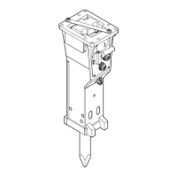
When fitting the top sub to the hammer, the clearance between the
top sub and the cylinder must be checked with a feeler gauge. This
is done as follows:
• Remove the control tube from the hammer. Fit back the other
parts and thread the top sub into the cylinder, tightening it by hand
only. The clearance between the top sub A and cylinder C must not
be less than 0,75 mm, then shims must be fitted.
Fitting the shims
Place 1-3 shims D (ordering NO:s: COP 32 / 3161-1146-00, COP 42 /
3161-1054-00) between the top sub A and valve body B as neces-
sary. After the shims have been fitted, the clearance between the
top sub and the cylinder should be between 1,5 and 2,5 mm.
• After the clearance have been checked and shims fitted (if neces
-
sary), the control tube must be fitted back into the hammer.
• If the clearance is less than 0,75 mm in spite of max. 3 shims
having been fitted, and if the top sub ahs been tightened by hand
only, this indicates that the compression ring E is worn and must
be changed.
• Finally, the top sub must be screwed firmly into the cylinder and
tightened with the aid of a rod spanner. The clearance between
the top sub and the cylinder should now have disappeared almost
completely.
Clearance before/after shimming
Ordering No�
shims (1–4)
Min�
clearance
Clearance after
shimning
COP 44 3161-1422-00 1,5 mm 1,9–2,5 mm
COP 54 3161-1522-00 1,8 mm 2,2–3,0 mm
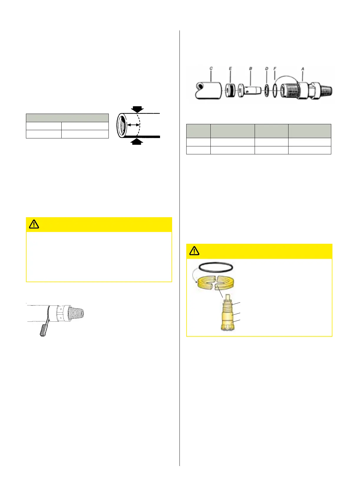
Assembly of the drill bit and driver chuck
• Smear the splines of the bit shank with Atlas Copco thread
grease.
• Smear the O-ring of the stop ring with silicone grease.
• Assemble the bit 1, driver chuck 2 and stop ring 3 as shown in
figure.
NB� The stop ring halves must be fitted so that the O-ring grooves
line up with each other. Make sure the stop ring faces the right
way.
3
2
1
Make sure the stop ring is located
correctly, and that it faces the
right direction. Incorrect fitting
will result in severe damage to
the hammer.
IMPORTANT
• Smear the thread on the driver chuck with Atlas Copco thread
grease.
• Screw in the bit assembly into the cylinder and tighten the driver
chuck securely with the aid of the special bit removal tool.
 Loading...