5
Preparing to drill
Hose connection
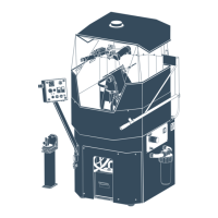
Connecting and securing the air hoses
For a compressed air system to
be efficient, reliable and
economic, there must be:
• sufficient compressed-air ca
-
pacity (volume and pressure);
• minimal pressure loss between
the compressor and the hammer;
• minimal air leakage between
couplings.
This can be realized by ensuring
that:
• the correct size of compressor
is selected;
• the correct hose size is used
between the compressor and the
hammer;
• there is no leakage in hose con
-
nections between the compres-
sor and hammer.
• Compressed-air hoses between the compressor and the
drill rig must be secured by means of an external or internal
safety wire, which must be fastened safely to the drill rig. If
the DTH hammer is to work at pressures above 10 bar (145
psi), any local regulations regarding air hoses and couplings
must be strictly observed.
• Always check that hoses, hose nipples and hose clamps
are not damaged, and that they are properly tightened and
secured.
DANGER
• Always check the condition of drill string components. Bent
or worn pipes can cause damage and excessive wear to the
hammer and rig.
CAUTION
Setting-up the rig
Before drilling with the DTH hammer, the rig must be set-up cor-
rectly in order to give stability and safety. If this is not done, the
effects of feed force and rotation torque can cause the rig to move.
This will have a negative effect on drilling, especially when drilling
deep, straight holes.
When setting up a drill wagon or crawler
drill rig, a stable three-point set-up must be
obtained, with the weight of the rig distrib-
uted between the base of the feed beam and
the two rear corners of the rig. It is of the
utmost importance that the rear loading
points are as far to the rear of the rig as
possible, with most of the rig weight being
loaded on to the base of the feed.
When drilling in soil or other non-consolidat-
ed formations, the weight of the rig must not
be loaded on to the feed near the mouth of
the hole, since this could easily cause the
hole to cave-in. Instead, the load should be
distributed some distance to either side of
the hole. Suitable support can be obtained
by placing a sturdy U-beam under the base
of the feed beam, and supporting the beam
on planks at both ends. A two inch (50 mm)
plank should then be placed inside the
U-beam to prevent mechanical chatter and
damage to the base of the feed beam.
If the rig is wheel-bound, it should be raised
off the ground completely using the jacks,
so that all wheels are clear of the ground.
• The rig must be set-up correctly in order to give stability
and safety. If this is not done, the effects of feed force and ro-
tation torque can cause the rig to move or even to overturn.
This can incur the risk of serious or fatal injury as well as
damage to the drill rig and equipment.
DANGER
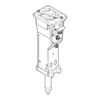
• Heavy lift. Take care when
handling the hammer. The
hammer and its internal
components are heavy and
difficult to handle, espe-
cially in the case of the
larger hammers.
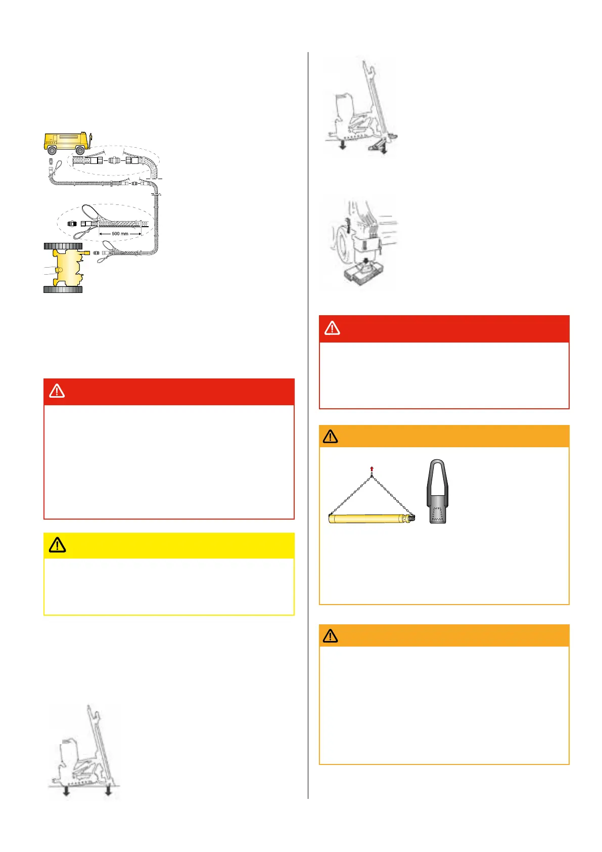
When lifting using mechanical lifting equipment, sling the
hammer as shown in the fig. Alternatively, a lifting-eye cou-
pling can be screwed on to the top sub.
• Transportation. Do not let the hammer lie unsecured on a vehi-
cle or drill rig. Al ways secure the hammer for transportation.
WARNING
• Always wear goggles during drilling!
• The exhaust air from the hammer (and also from the top
sub if a unit for extra flushing is fitted) has a very high
velocity. Objects such as small stones, drill cuttings, sand,
earth and oil residue that are entrained in the flushing air
can cause serious injury to unprotected eyes. Pay special
attention to this danger during collaring, when a top sub with
extra flushing is in use, an when the hammer is fed through
the drill steel support or down into the hole.
WARNING
 Loading...