V DMA BLOCK: IDMA (Intelligent DMA)
B-V-3-8 EPSON S1C33L03 FUNCTION PART
Operation of IDMA
IDMA has three transfer modes, in each of which data transfer operates differently. Furthermore, an interrupt factor
is processed differently depending on the type of trigger. The following describes the operation of IDMA in each
transfer mode and how an interrupt factor is processed for each type of trigger.
Single transfer mode
The channels for which DMOD in control information is set to "00" operate in single transfer mode. In this
mode, a transfer operation invoked by one trigger is completed after transferring one data unit of the size set
by DATSIZ. If a data transfer needs to be performed a number of times as set by the transfer counter, an
equal number of triggers are required.
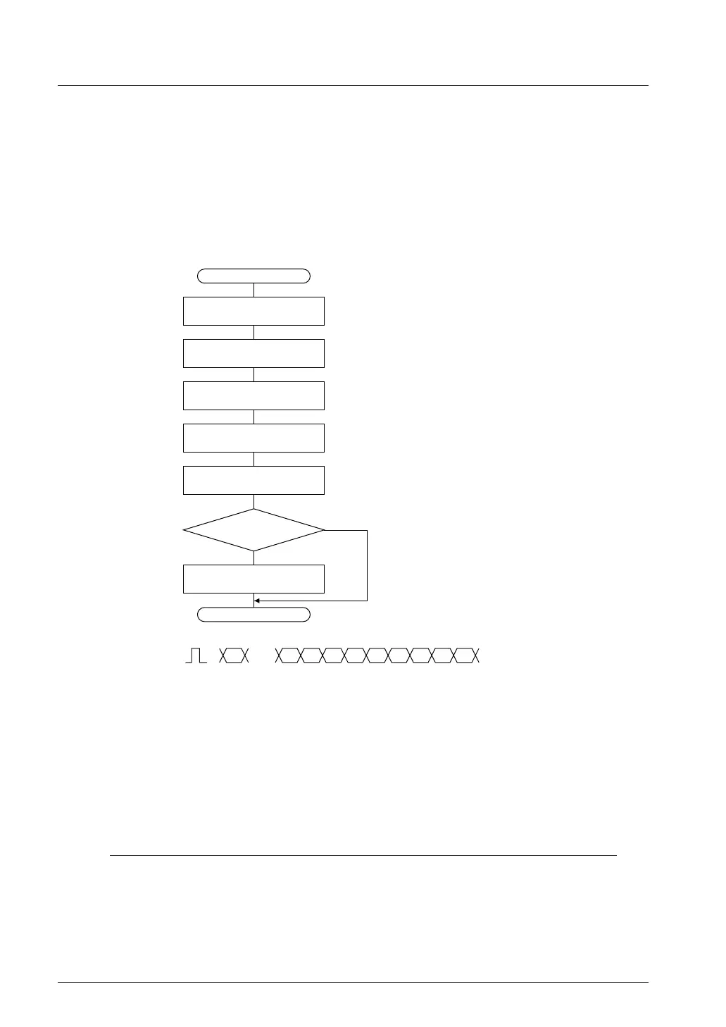
The operation of IDMA in single transfer mode is shown by the flow chart in Figure 3.1.
START
END
Calculates address of
control information
Loads channel
control information
Transfers one unit of data
Transfer counter - 1
Saves channel
control information
IDMA interrupt processing
(if interrupt is enabled)
Transfer
counter = 0
A
Base address + (Channel number × 12)
B (3 words)
C (Data read from source of transfer)
D (Data write to destination of transfer)
E
F (3 words)
N
Trigger
Y
A B1 B2 B3 C D E F1 F2 F3
Figure 3.1 Operation Flow in Single Transfer Mode
(1) When a trigger is accepted, the address for control information is calculated from the base address and
channel number.
(2) Control information is read from the calculated address into the internal temporary register.
(3) Data of the size set in the control information is read from the source address.
(4) The read data is written to the destination address.
(5) The address is incremented or decremented and the transfer counter is decremented.
(6) The modified control information is written to RAM.
(7) In the case of a hardware trigger, the interrupt control bits are processed before completing IDMA.
Condition Interrupt factor flag IDMA request bit IDMA enable bit
Transfer counter ≠ "0": Reset ("0") Not changed ("1") Not changed ("1")
Transfer counter = "0", DINTEN = "1": Not changed ("1") Reset ("0") Not changed ("1")
Transfer counter = "0", DINTEN = "0": Reset ("0") Not changed ("1") Reset ("0")
 Loading...