+
−
+
−
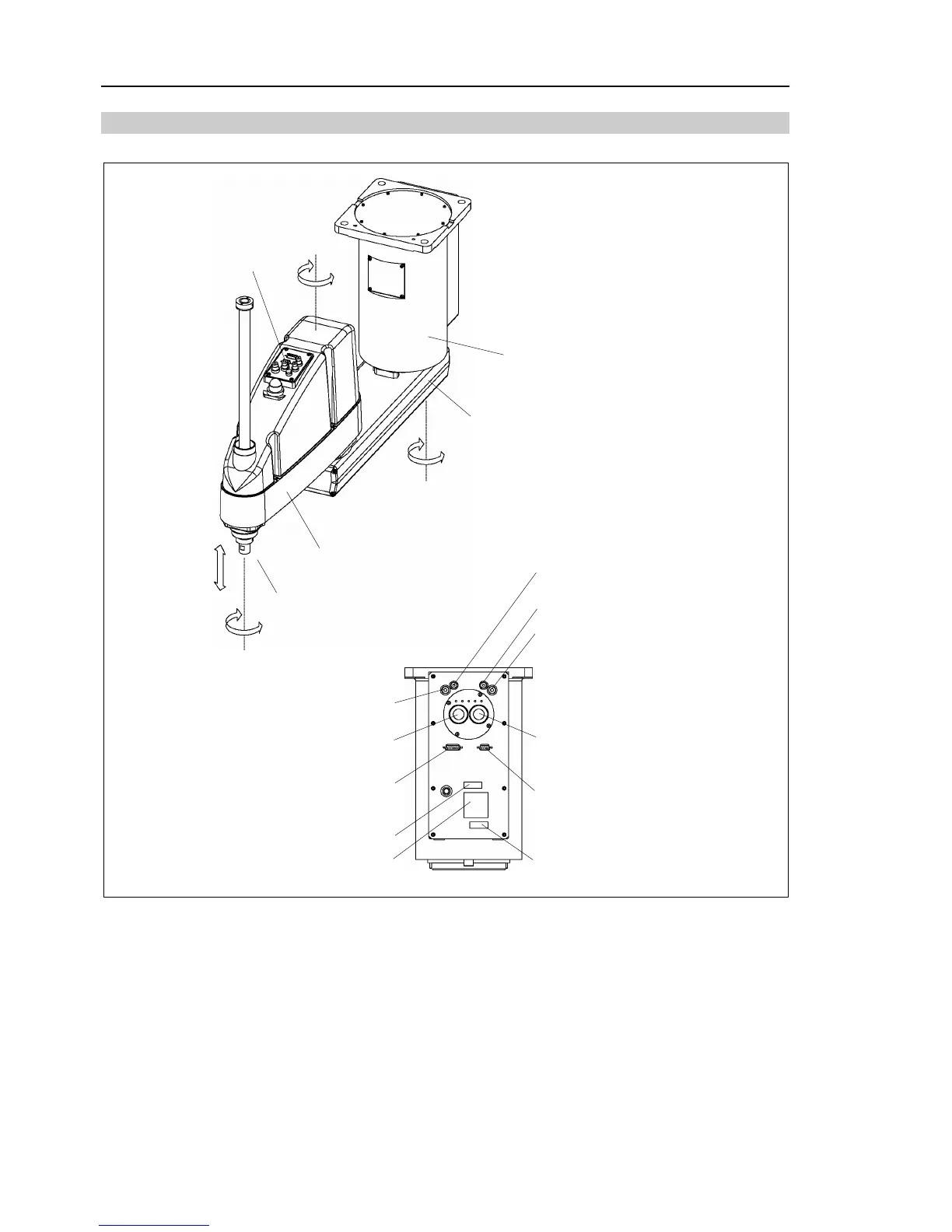
Joint #3
(up and down)
Joint #2
(rotating)
Joint #1
(rotating)
Joint #4
(rotating)
Arm #2
Arm #1
Joint #3 and #4
brake release button
Base
Shaft
MT label
(only for custom specification)
Signature label
(Serial No. of Manipulator)
CE label
Signal cable
Power cable
Fitting (black)
for ø 4 mm pneumatic tube
User connector
(15-pin D-sub connector)
User connector
(9-pin D-sub connector)
Fitting (white)
for ø4 mm pneumatic tube
Fitting (white)
for ø 6 mm pneumatic tube
Fitting (black)
for ø 6 mm pneumatic tube
The brake release button affects both Joints #3 and #4. When the brake release button is pressed in
emergency mode, the brakes for both Joints #3 and #4 are released simultaneously. (For G6-**1**,
Joint #4 has no brake on it.)
)
NOTE
 Loading...


