Setup & Operation 5. Motion Range
G10 / G20 Rev.2 59
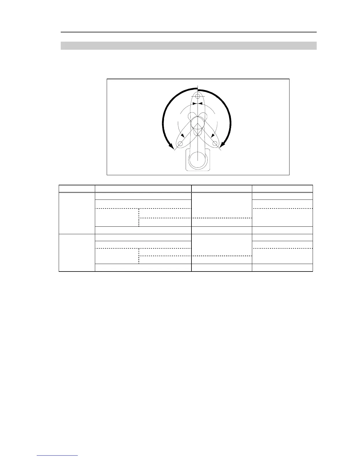
5.1.2 Max. Pulse Range of Joint #2
The 0 (zero) pulse position of Joint #2 is the position where Arm #2 is in-line with Arm #1.
With the 0 pulse as a starting point, the counterclockwise pulse value is defined as the
positive (+) and the clockwise pulse value is defined as the negative (-).
B B
0 pulse
A A
Model Table Top Mounting Ceiling / Wall Mountings
G10-65*S*
±130 degrees
G10 / G20-85*S*
±152.5 degrees
Z: 0 to −360
±152.5 degrees
G10 / G20-85*C*
Z:
−360 to −390
±151 degrees
±151 degrees
A
Max. Motion
Range
G20-A0*S*
±152.5 degrees ±152.5 degrees
G10-65*S*
±2366578
G10 / G20-85*S*
±2776178
Z: 0 to −360
±2776178
G10 / G20-85*C*
Z:
−360 to −390
±2748871
±2748871
B
Max. Pulse
Range
G20-A0*S*
±2776178
±2776178
)
NOTE
In the range Z: –360 to –390 mm, the area is limited by interference of the Manipulator body and the arm.
 Loading...


