11 12
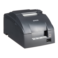
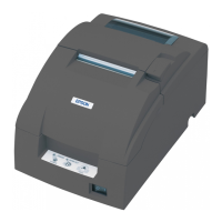
TM-U220A
Specification
(For Argentina Fiscal)
1
6
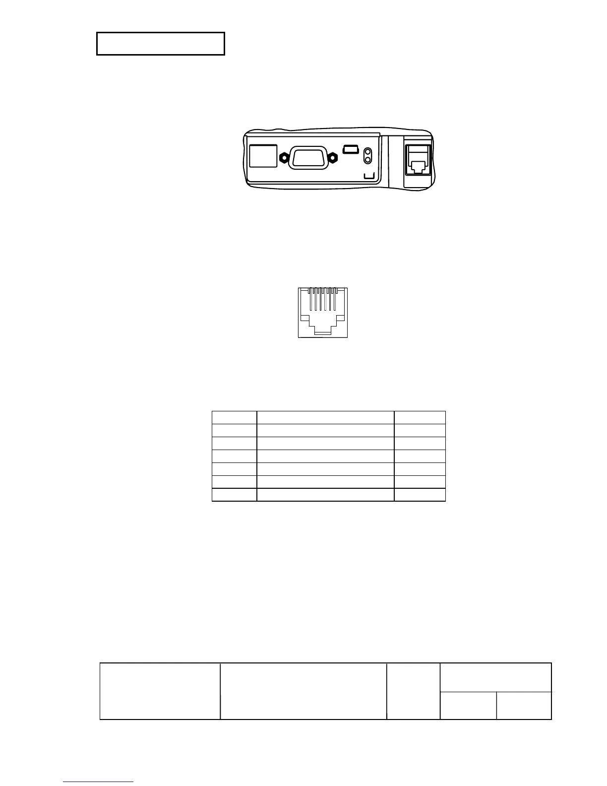
2.3 Connectors
2.3.1 Interface connectors
See Section 2.1, Interfaces.
Figure 2.3.1 Panel Diagram
2.3.2 Drawer kick-out connector (Modular connector)
The pulse specified by the ESC p or DLE DC4 is output to this connector. The host PC can confirm
the status of the input signal by using the
DLE EOT, GS a, or GS r commands.
1) Pin assignments
+24 V is output through pin 4 when the power is turned on. However, pin 4 must be used only for
the drawer.
Figure 2.3.2 Drawer Kick-out Connector
Table 2.3.1 Drawer Kick-out Connector Pin Assignments
Pin No. Signal Name Direction
1 Frame GND --
2 Drawer kick-out drive signal 1 Output
3 Drawer open/close signal Input
4 +24 V --
5 Drawer kick-out drive signal 2 Output
6 Signal GND --
2) Connector model: Printer side: DDK 285D-7660J-100 or the equivalent
User side: 6-position 6-contact (RJ12 telephone jack)
 Loading...