www.fastech.co.kr
6. External Name and Function Setting of Ezi-SERVO-PR
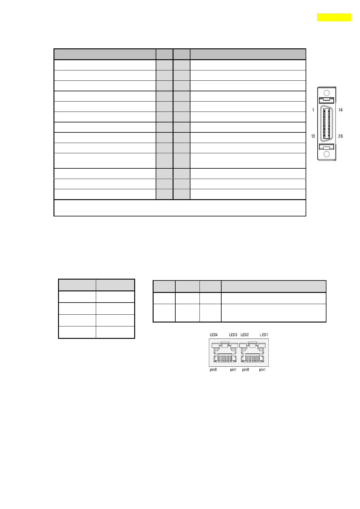
6.9 Communication Connecttion (CN5)
Connector Type : RJ45
Cable Type : UTP/STP CAT5E
Digital In2 ( Programmable Input)
Digital In3 ( Programmable Input)
Digital In4 ( Programmable Input)
Digital In1 (Programmable Input)
Digital In5 ( Programmable Input)
Digital In6 (Programmable Input)
Digital In8 ( Programmable Input)
Digital In7 (Programmable Input)
Digital In9 ( Programmable Input)
Compare Out/COMP (Dedicated Output)
Digital Out7 ( Programmable Output)
Digital Out1 (Programmable Output)
Digital Out8 ( Programmable Output)
Digital Out2 (Programmable Output)
Digital Out9 ( Programmable Output)
Digital Out3 (Programmable Output)
+24V for Brake system(Output)
Digital Out4 (Programmable Output)
Control signal of Brake system(Output)
Digital Out5 (Programmable Output)
Digital Out6 (Programmable Output)
* This connector fixed pin is connected to frame GND through a mount hall.
Flash when CPU in the drive operates
Flash when this communicates with the
upper controller
 Loading...