EasyManua.ls Logo

Fastech Ezi-Servo ALL User Manual

Default Icon
104 pages
To Next Page IconTo Next Page
To Previous Page IconTo Previous Page
Page #68 background imageLoading...
Page #68 background image
www.fastech.co.kr
68
11. Operation
11. Operation
11.1 Power Supply Timing
Ezi-SERVO Plus-R is supplied power through drive module to motor. Therefore, connect the
drive and the motor with a cable and then supply power to the drive module. After power is
supplied, the motor is basically set to Servo OFF.
11.2 Servo ON Operation
After power is supplied, set the drive module to Servo ON as follows.
Click Servo OFF button at the User Program(GUI).
Give the drive a command through DLL library.
Assign Servo ON to a control input pin, and supply the drive with the signal through
the pin.
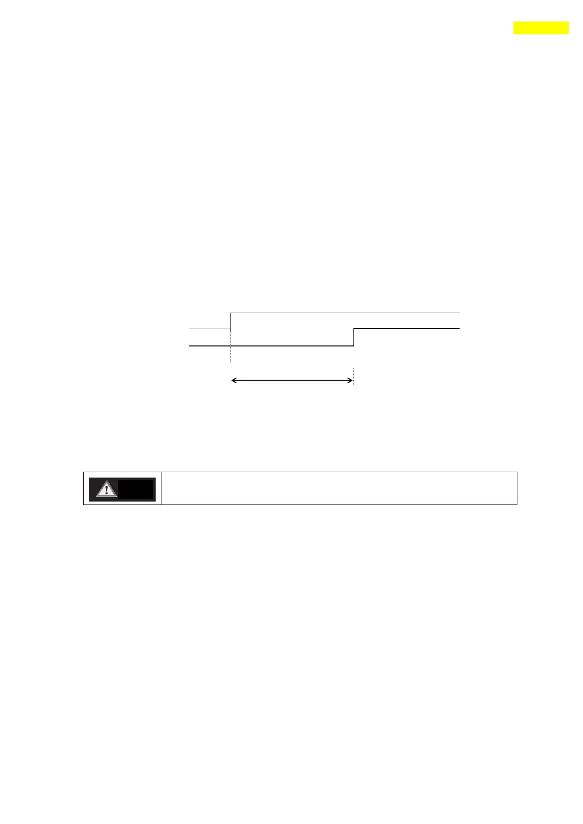
After Servo ON command is given, In-position is finished to the time as shown below.
t1 is the time until Servo ON command is given and then the position is decided. It is
about 400 [msec] with factory default value and it can be change with Servo ON Method
[No.33] parameter. It is subject to the rising time of supplying power and the motor
status.
If the Servo ON signal is assigned to input pin, ServoON command
from GUI or DLL library will not executed.
11.3 Operation Mode
This controller can do three control operations such as I/O command, communication
command(DLL program), and User Program(GUI)
(1) I/O Command Mode
This controller can execute control operation like in-position by I/O command
transmitted from the upper controller. The in-position control operation is executed by
operating position table with I/O command.
(2) Communication Command Mode
This controller can execute control operation like in-position by command transmitted
from the upper controller. The in-position control operation is executed by operating
position table with I/O command
Servo ON command
t1
Position Set
Caution

Table of Contents

Question and Answer IconNeed help?

Do you have a question about the Fastech Ezi-Servo ALL and is the answer not in the manual?

Fastech Ezi-Servo ALL Specifications

General IconGeneral
Control ModePosition, Velocity, Torque
FeedbackIncremental Encoder
Input Voltage24VDC
Communication InterfaceRS-485, CANopen
Supply Voltage24 VDC
CommunicationRS-485
Protection FeaturesOvercurrent, Overvoltage, Overheat
Operating Temperature0°C to 40°C
Storage Temperature-20°C to 60°C
Humidity20% to 85% RH, non-condensing

Summary

Safety Pre-cautions

Precautions

General safety advice for handling, installation, and operation of the drive.

Check the Product

Guidelines for inspecting the product for damage or missing parts before use.

Installation

Instructions and precautions for safely installing the drive unit.

Connect Cables

Safety guidelines for connecting input power and signal cables.

Operation Safety

Safety advice related to operating the drive and handling potential alarms.

Specifications of the Drive

Characteristic Table

Detailed specifications for Ezi-SERVO-PR, PR-MI, and ALL series drives.

Dimensions

Physical dimensions for Ezi-SERVO-PR, PR-MI, and ALL series drives.

Specifications of the Motor

EzM-20 Series Specifications

Electrical and mechanical specifications for EzM-20 series motors.

EzM-20 Series Dimensions

Physical dimensions for EzM-20 series motors.

EzM-28 Series Specifications

Electrical and mechanical specifications for EzM-28 series motors.

EzM-28 Series Dimensions

Physical dimensions for EzM-28 series motors.

EzM-35 Series Specifications

Electrical and mechanical specifications for EzM-35 series motors.

EzM-35 Series Dimensions

Physical dimensions for EzM-35 series motors.

EzM-42 Series Specifications

Electrical and mechanical specifications for EzM-42 series motors.

EzM-42 Series Dimensions

Physical dimensions for EzM-42 series motors.

Ezi-SERVO-ALL Series Dimensions

Physical dimensions for Ezi-SERVO-ALL series motors.

EzM-56 Series Specifications

Electrical and mechanical specifications for EzM-56 series motors.

EzM-56 Series Dimensions

Physical dimensions for EzM-56 series motors.

Ezi-SERVO-ALL Series Dimensions (cont.)

Physical dimensions for Ezi-SERVO-ALL series motors.

EzM-60 Series Specifications

Electrical and mechanical specifications for EzM-60 series motors.

EzM-60 Series Dimensions

Physical dimensions for EzM-60 series motors.

Ezi-SERVO-ALL Series Dimensions (cont. 2)

Physical dimensions for Ezi-SERVO-ALL series motors.

EzM-86 Series Specifications

Electrical and mechanical specifications for EzM-86 series motors.

EzM-86 Series Dimensions

Physical dimensions for EzM-86 series motors.

Characteristics of Motor Torque

Ezi-SERVO-PR Torque Characteristics

Torque vs. speed graphs for Ezi-SERVO-PR series motors.

Ezi-SERVO PR-MI Torque Characteristics

Torque vs. speed graphs for Ezi-SERVO PR-MI series motors.

Ezi-SERVO-ALL Torque Characteristics

Torque vs. speed graphs for Ezi-SERVO-ALL series motors.

Controller Configuration

Motor and Drive Combination

Explains model naming conventions for Ezi-SERVO-PR, PR-MI, and ALL series.

Ezi-SERVO-PR Controller Configuration

Wiring diagram for Ezi-SERVO-PR series controllers.

Ezi-SERVO-PR86 & PR-MI Controller Configuration

Wiring diagrams for Ezi-SERVO-PR86 and PR-MI controllers.

Ezi-SERVO-ALL Series Controller Configuration

Wiring diagrams for Ezi-SERVO-ALL series controllers.

External Wiring Diagram: Ezi-SERVO-PR Series

Detailed wiring for Ezi-SERVO-PR series controllers.

External Wiring Diagram: Ezi-SERVO-PR86

Detailed wiring for Ezi-SERVO-PR86 controllers.

External Wiring Diagram: Ezi-SERVO-PR-MI

Detailed wiring for Ezi-SERVO-PR-MI controllers.

External Wiring Diagram: Ezi-SERVO-ALL42/56

Detailed wiring for Ezi-SERVO-ALL42/56 controllers.

External Wiring Diagram: Ezi-SERVO-ALL60

Detailed wiring for Ezi-SERVO-ALL60 controllers.

External Wiring Diagram: Ezi-SERVO-ALL60-ABS

Detailed wiring for Ezi-SERVO-ALL60-ABS controllers.

External Name and Function Setting of Ezi-SERVO-PR

Appearance and Part Name

Identifies external components and connectors of Ezi-SERVO-PR and PR86.

Status Display LED

Explains the meaning of status LEDs on the drive.

Drive ID Switch Selection (SW1)

Configuration of drive ID using DIP switches.

Communication Speed and Terminal Resistance Switch (SW2)

Settings for communication speed and terminal resistance.

Motor Connection (CN3)

Details the pinout for motor connection.

Encoder Connection (CN2)

Details the pinout for encoder connection.

Power Connection (CN4)

Details the pinout for power connection.

I/O Signal Connection (CN1)

Details the pinout for I/O signals.

Communication Connection (CN5)

Details the pinout for communication connection.

External Name and Function Setting of Ezi-SERVO-PR-MI

Appearance and Part Name

Identifies external components and connectors of Ezi-SERVO-PR-MI.

Drive ID Switch Selection (SW1)

Configuration of drive ID using DIP switches and 7-segment display.

Communication Speed and Terminal Resistance Switch (SW2)

Settings for communication speed and terminal resistance.

Motor Connection (CN3)

Details the pinout for motor connection.

Encoder Connection (CN2)

Details the pinout for encoder connection.

Power Connection (CN4)

Details the pinout for power connection.

I/O Signal Connection (CN1)

Details the pinout for I/O signals.

Communication Connection (CN5)

Details the pinout for communication connection.

External Name and Function Setting of Ezi-SERVO-ALL42 / ALL56

Appearance and Part Name

Identifies external components and connectors of Ezi-SERVO-ALL42/56.

Terminal Resistance Select Switch (SW1)

Configuration of terminal resistance for RS-485 communication.

Drive ID Switch Selection (SW2)

Configuration of drive ID using DIP switches.

Communication Speed Select Switch (SW3)

Settings for communication speed.

I/O Signal Connection (CN1)

Details the pinout for I/O signals.

Power Connection (CN2)

Details the pinout for power connection.

Communication Connection (CN3, CN4)

Details the pinout for communication connection.

External Name and Function Setting of Ezi-SERVO-ALL60

Appearance and Part Name

Identifies external components and connectors of Ezi-SERVO-ALL60.

Terminal Resistance Select Switch (SW1)

Configuration of terminal resistance for RS-485 communication.

I/O Signal Connection (CN3)

Details the pinout for I/O signals.

Power Connection (CN1)

Details the pinout for power connection.

Communication Connection (CN5, CN6)

Details the pinout for communication connection.

Control I/O Signal

Signal Cabling (Ezi-SERVO-PR type)

Details input/output signal connections for Ezi-SERVO-PR.

Signal Cabling (Ezi-SERVO-ALL type)

Details input/output signal connections for Ezi-SERVO-ALL.

Connection Circuit: Input

Explains input circuit design and NPN/PNP signal connection.

Connection Circuit: Output

Explains output circuit design and specifications.

Input Signals

Details various input signals like Limit, Origin, Clear Pos, Position Table.

Output Signals

Details output signals like Compare Out, Inposition, Alarm, AlarmBlink.

Operation

Power Supply Timing

Sequence for supplying power to the drive and motor.

Servo ON Operation

Steps to set the drive module to Servo ON mode.

Operation Mode

Describes I/O, Communication, and GUI control modes.

Position Table Operation

How to execute continuous operation using position tables.

Stopping Continuous Operation

Methods to stop position table operations.

Position Control Operation

Operating the motor using parameters, overriding PT operations.

Teaching Function

How to teach position values using the GUI.

Other Operation Functions

Position Table (PT) Operation Example

Demonstrates setting PT numbers and executing operations.

Jog Operation Example

Demonstrates speed control using Jog signals.

Origin Return

Explains how to perform origin return using I/O or software.

Stop Operation

How to input stop and emergency stop commands.

Trigger Pulse Output

Setting up periodic output signals for absolute coordinate systems.

Push Motion

Using specified motor torque during motion or stop.

Communication Function

Connection with the PC

Methods for connecting the drive to a PC via RS-485.

RS-485 Converter and Drive Module Cables

Details cables for connecting RS-485 converters to drives.

Communication Interface Circuit

Explains the I/O circuit for RS-485 communication.

Protective Function

Alarm Type

Lists alarm types based on LED flash counts.

Acquiring Alarm Information

How to interpret alarm signals and LED flashes.

Alarm Check and Release

Procedures to identify, resolve, and release alarms.

Alarm Log

Information on storing and viewing alarm logs.

Parameter

Parameter List

Comprehensive list of all adjustable parameters with their ranges.

Encoder Setup

Configuration of encoder resolution and related settings.

Parameter Description

Detailed explanation of each parameter's function and settings.

Appendix

RS-485 Communication Options

Information on RS-485 converters and cables.

RS-485 Cables for PR-MI/ALL Series

Details RS-485 cables for PR-MI and ALL series.

Interface Board Options (Ezi-SERVO-PR)

Details terminal blocks and extension cables for interface boards.

Motor Drive Cables (Ezi-SERVO-PR)

Lists cables for I/O, power, and motor connections.

Encoder Extension Cable (Ezi-SERVO-PR)

Details extension cables for encoders.

Connector Specifications

Lists specifications for various connectors used.

Motor Drive Cables (Ezi-SERVO-PR-MI)

Lists cables for I/O, power, and motor for PR-MI.

Encoder Extension Cable (Ezi-SERVO-PR-MI)

Details extension cables for encoders for PR-MI.

Connector Specifications (Ezi-SERVO-PR-MI)

Lists connector specifications for PR-MI.

Motor Drive Cables (Ezi-SERVO-ALL42/56)

Lists cables for I/O, power for ALL42/56.

Motor Drive Cables (Ezi-SERVO-ALL60)

Lists cables for I/O, power for ALL60.

Related product manuals