www.fastech.co.kr
10. Control I/O Signal
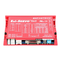
10.1 Signal Cabling (Ezi-SERVO-PR type)
All control I/O signals use connector CN1 as specified below.
1) Input : 「Limit+」, 「Limit-」, 「Origin」 signals are fixed to CN1 No. 1,2,3.
Other signals as like ‘Clear Pos’are assigned to IN1~IN9 terminal blocks.
(3 dedicated input + 9 programmable input = total 12 input pins.)
Ezi-SRERVO-PR : 3 dedicated In + 9 programmable In = 12 Inputs
Ezi-SRERVO-PR-MI : 3 dedicated In + 7 programmable In = 10 Inputs
Positive limit sensor signal
Negative limit sensor signal
Clear Pos
Position table A0 ~ Position table A7 (PT A0~PT A7)
Position table start execution (PT Start)
Soft Stop(Stop)
Jog+
Jog-
AlarmReset
ServoON
Pause
Origin Search
Teaching
Emergency Stop(E-Stop)
Jump Position Table input 0 ~ Jump Position Table input 2
(JPT IN 0~ JPT IN 2)
Jump Position Table start (JPT Start)
User input 0 ~ User input 8 (User IN 0 ~ User IN 8)
2) Output : 「COMP」 signal is dedicated to CN1 No.7. Other signals like
Inposition are assigned to OUT1~OUT9 terminal blocks.
Ezi-SRERVO-PR : 1 dedicated Out + 9 programmable Out = 10 Outputs
Ezi-SRERVO-PR-MI : 1 dedicated Out + 1 programmable Out = 2 Outputs
Specific output signal (Compare Out)
InPosition
Alarm
Moving
Acc/Dec
ACK
END
AlarmBlink
OriginSearchOK
ServoReady
Brake
Position Table output 0 ~ Position Table output 2
(PT OUT 0 ~ PT OUT 2)
User Output 0 ~ User Output 8
 Loading...