Manual No. 016-5030-043 Rev. A 21
Node and Wiring Installation
5. Secure the node to the mounting bracket assembly using three 3/8”-16 flanged lock nuts (P/N 312-1001-
167).
Vario 900 Series Mounting
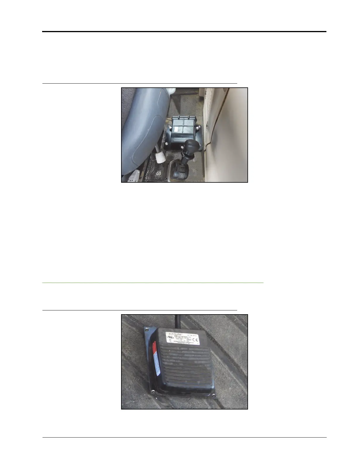
FIGURE 4. Node Installed
Note: The forward vehicle direction is 1 in the pictured node orientation.
1. Place the node mounting bracket (P/N 107-0172-084) on the floor of the cab to the left of the operator’s
seat, behind the parking brake.
2. Secure the bracket to the floor of the cab using four #10-16 x 3/4” self-tapping screws (P/N 310-1002-073)
and four 0.265” ID x 0.505” OD x 0.060” thick washers (P/N 313-2300-120) or six strips of double-sided
tape (P/N 332-0000-019).
3. Secure the node (P/N 063-4001-013) to the node mounting bracket using three 3/8”-16 zinc flanged lock
nuts (P/N 312-1001-167).
Install the Foot Switch
FIGURE 5. Foot Switch Installed
 Loading...