SHOP MANUAL
Paragraphs 26-27
ENGINE AND COMPONENTS
R&R ENGINE ASSEMBLY
All Models
26.
To
remove engine assembly, first
drain coolant from radiator, drain
hy-
draulic
oil
from transmission housing,
and drain engine
oil if
engine
is to be
disassembled. Remove front
end
weights
if so
equipped. Disconnect
and
remove
the
battery. Remove
the
hood
assembly. Disconnect upper
and
lower
radiator hoses and remove radiator sup-
port brace
if
used. Remove
air
cleaner
hose.
Disconnect steering drag link (except
1710 Offset model) from pitman arm. On
1710 Offset, remove cap screws attach-
ing steering column
to
upper support
bracket
and
disconnect power steering
(if equipped) supply and return lines. On
models with hydrostatic transmission,
disconnect oil lines from transmission oil
cooler filter manifold.
Install wood wedges between front
support frame rails
and
front axle
to
prevent tipping. Attach
a
hoist to engine
lift brackets
and
place suitable support
stand under clutc^h housing.
If
equipped
with front wheel drive axle, place front
drive control lever
in
disengaged posi-
tion and loosen drive shaft cover clamps
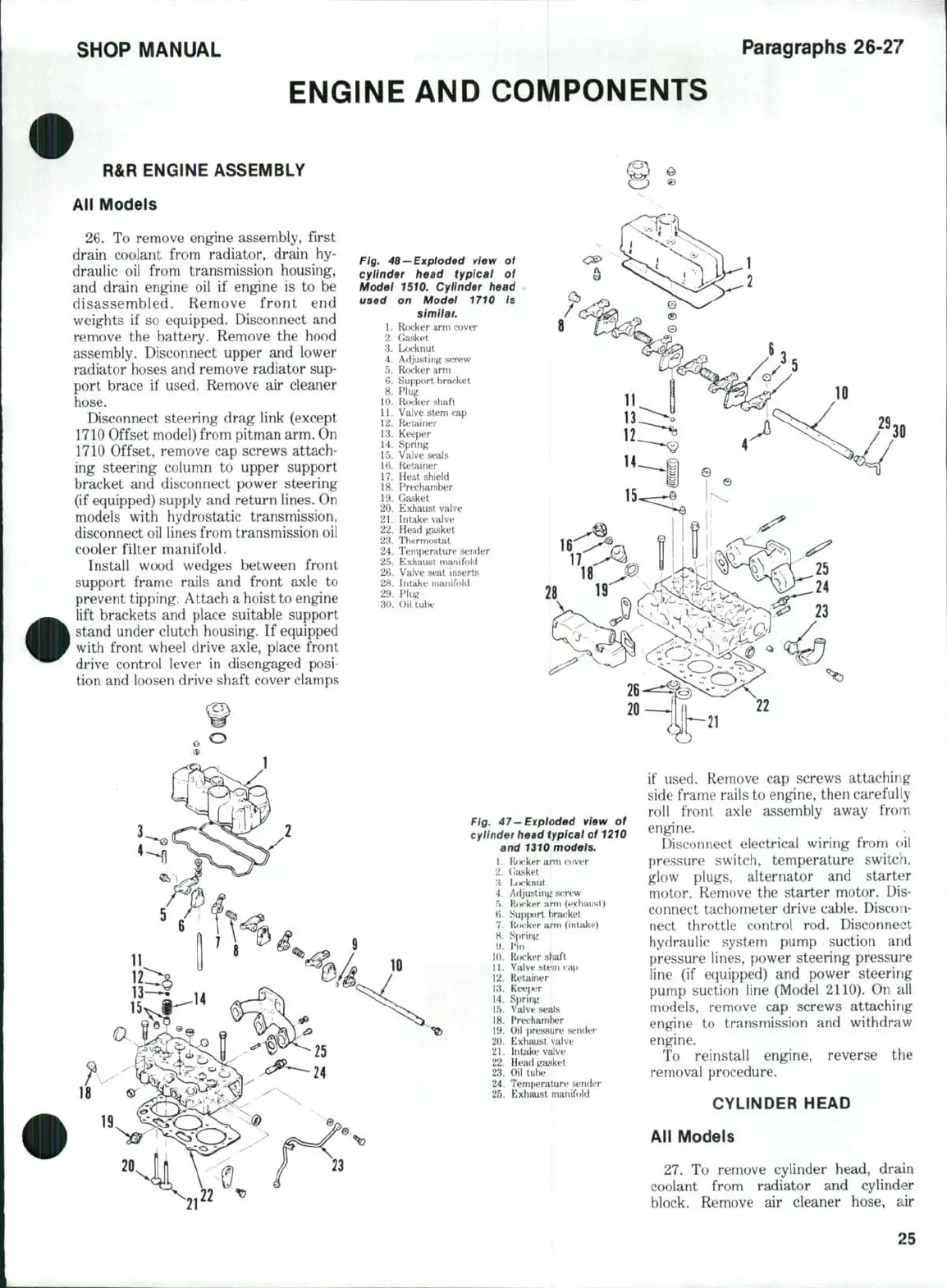
Fig. 46-Exploded view of
cylinder head typical of
Model 1510. Cylinder head
used on Model 1710 is
similar.
1.
Rocker arm cover
2.
Gasket
3.
Locknut
4.
Adjusting screw
5.
Rocker arm
6. Support bracket
8. Plug
10.
Rocker shaft
11.
Valve stem cap
12.
Retainer
13.
Keeper
14.
Spring
15.
Valve J
i seals
16.
Retainer
17.
Heat sbield
18.
Precbamber
19.
Gasket
20.
Exhaust valve
21.
Intake valve
22.
Head gasket
23.
Thermostat
24.
Temperature sender
25.
Exhaust manifold
26.
Valve seat inserts
28.
Intake manifold
29.
Plug
30.
Oii tube
Fig. 47-Exploded view of
cylinder head typical of 1210
and 1310 models.
1.
RiK'ker arm cover
2.
Gasket
3.
b>ckiiul
4.
Adjusting screw
.^j.
Rocker arm (exhaust)
B.
SupjMtrt bracket
7.
Roi-ker arm (iiitake)
8. Spriti^r
9.
Pin
10.
RcK'ker shaft
11.
Valve stem
rap
12.
Retainer
13.
Keef)er
14.
Sprin;;
15.
Valve seals
18.
Prechamlier
19.
Oil pressure sender
20.
Exbaust valve
21.
Intake valve
22.
Head gasket
23.
Oil tube
24.
Temf)eraturt' sender
25.
Exbaust manifold
if used. Remove
cap
screws attaching
side frame rails to engine, then carefully
roll front axle assembly away from
engine.
Disconnect electrical wiring from c>il
pressure switch, temperature switch,
glow plugs, alternator
and
starter
motor. Remove
the
starter motor.
Dis-
connect tachometer drive cable. Discon-
nect throttle control
rod.
Disconnect
hydraulic system pump suction
and
pressure lines, power steering pressure
line
(if
equipped)
and
power steering
pump suction line (Model 2110).
On all
models, remove
cap
screws attaching
engine
to
transmission
and
withdraw
engine.
To reinstall engine, reverse
the
removal procedure,
CYLINDER HEAD
All Models
27.
To
remove cylinder head, drain
coolant from radiator
and
cylinder
block. Remove
air
cleaner hose,
air
25
 Loading...
