SHOP MANUAL
Paragraphs 82-88
Clean exterior surfaces with a brass
wire brush, soaking in an approved car-
bon solvent if necessary, to loosen hard
carbon deposits. Rinse parts in clean
diesel fuel or calibrating oil immediately
after cleaning to neutralize the solvent
and prevent etching of polished sur-
faces.
Clean nozzle spray orifice hole using
1.0 mm (0,040 inch) wire in a pin vise.
Scrape carbon from pressure chamber
using hooked scraper. Clean valve seat
using brass scraper.
Reclean all parts by rinsing thoroughly
in clean diesel fuel or calibrating oil and
assemble while parts are immersed in
cleaning fluid. Make sure adjusting shim
pack is intact. Tighten nozzle retaining
nut (3) to a torque of 61-75 N-m (45-55
ft.-lbs.).
Do not overtighten, distortion
may cause valve to stick and no amount
of overtightening can stop a leak caused
by scratches or dirt. Retest assembled
injector as previously outlined.
GLOW PLUGS
All Models
82.
Glow plugs are parallel connected
with each glow plug grounding through
mounting threads. Start switch is pro-
vided with a "HEAT" position which can
be used to energize the glow plugs for
faster warm up. If "COLD START AID"
indicator light fails to glow when start
switch is held in "HEAT" position an ap-
propriate length of time (approximately
30 seconds), check for loose connections
at switch, indicator lamp, glow plug con-
nections and ground. A test lamp can be
used at glow plug connection to check
for current to glow plug.
COOLING SYSTEM
All models use a pressurized cooling
system which raises coolant boiling
point. An impeller type centrifugal
pump is used to provide forced circula-
tion, A thermostat is used to stabilize
operating temperature.
RADIATOR
All Models
85.
Radiator cap pressure valve is set
to open at 90 kPa (13 psi) on all models.
It is recommended that a 50/50 mix of
ethylene glycol base antifreeze and
water be used for coolant. Refer to
2
FIQ.
142—
Exploded view of water pump used on
1100, 1110, 1200 and 1300 modeis. Thermostat
(2) is aiso shown.
1,
Thermostat housing
2.
Thermostat
4.
"0" ring
5.
Impeller
6. Seal assy.
7.
8.
10.
11,
12.
Housing
Shaft
&
bearing assy
Pulley huh
Spacer
Fan
CONDENSED SERVICE DATA sec-
tion for cooling system capacities.
To remove radiator, first drain the
coolant. Remove upper and lower radia-
tor hoses. Remove air cleaner hose if
necessary. Unbolt and remove radiator
assembly.
THERMOSTAT
All Models
86.
The thermostat is located in the
coolant outlet elbow on all models except
1210 and 1310 models. On 1210 and
1310 models, the thermostat is located
in the water pump housing. On all
models, thermostat should begin to open
at 7r C (160° F) and be completely
open at
85"*
C (185° F),
WATER PUMP
Models 1100-1110-1200-1300
87.
R&R AND OVERHAUL. To
remove water pump, first drain coolant
from radiator and cylinder block.
Loosen alternator attaching bolts and
remove fan belt. Remove radiator and
cooling fan. Remove water pump mount-
ing bolts and remove the pump.
To disassemble, pull drive pulley
(10-Fig. 142) off pump shaft. Support
pump housing, then press shaft and
bearing assembly (8) forward out of im-
peller
(5)
and pump housing. Remove the
seal assembly (6).
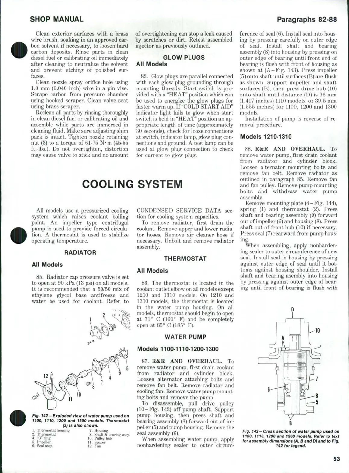
When assembling water pump, apply
nonhardening sealer to outer circum-
ference of seal (6). Install seal into hous-
ing by pressing carefully on outer edge
of seal. Install shaft and bearing
assembly (8) into housing by pressing on
outer edge of bearing until front end of
bearing is flush with front of housing as
shown at (A-Fig. 143). Press impeller
(5) onto shaft until surfaces (B) are flush
as shown. Support impeller and shaft
surfaces (B), then press drive hub (10)
onto shaft until distance (D) is 36 mm
(1.417 inches) UK) models, or 39.5 mm
(L555 inches) for 1100, 1200 and 1300
models.
Installation of pump is reverse of re-
moval procedure.
Models 1210-1310
88.
R&R AND OVERHAUL. To
remove water pump, first drain coolant
from radiator and cylinder block.
Loosen alternator mounting bolts and
remove fan belt. Remove radiator as
outlined in paragraph 85. Remove fan
and fan pulley. Remove pump mounting
bolts and withdraw water pump
assembly.
Remove mounting plate (4-Fig. 144),
spring (1) and thermostat (2). Press
shaft and bearing assembly (9) forward
out of impeller (6) and housing
(8).
Press
shaft out of front hub (10) if necessary.
Press seal (7) rearward from pump hous-
ing.
When assembling, apply nonharden-
ing sealer to outer circumference of new
seal. Install seal in housing by pressing
against outer edge of seal until it bot-
toms against housing shoulder. Install
shaft and bearing asembly into housing
by pressing against outer edge of bear-
ing until front of bearing is flush with
10
Fig.
143—
Cross
section of water pump used on
1100, 1110, 1200 and 1300 models. Refer to text
for assembiy dimensions
(A,
B and D) and to Fig.
142 for legend.
53
 Loading...
