SHOP MANUAL
Paragraph
28
now available
in two
different thick-
nesses
to set
piston
to
cylinder head
•clearance. The thicker head gasket
is to
be used
on
engines that were equipped
with both
a
gasket and shims. The thin-
ner gasket
is to
be used on engines that
were equipped with
a
gasket
and no
shims.
For
identification purposes,
the
last four digits
of
head gasket part
number
are
stamped
on
the gasket.
On 1100, 1210, 1310, 1510, 1710, 1910
and 2110 models, head gaskets
of
differ-
ent thicknesses
are
available
for
serv-
ice
and
selection
of
correct gasket
thickness
is
based
on the
distance pis-
tons protrude above face
of
cylinder
block
at
TDC.
Use a
dial indicator
or
other suitable means to measure height
of each piston above cylinder block sur-
face as shown
in
Fig. 50. Use the meas-
urement from piston that
has the
highest protrusion
and
select
ap-
propriate thickness head gasket
as in-
dicated
in
chart shown
in
Fig.
51.
NOTE:
On 1210 and 1310 models, the
head gasket thickness is stamped on the
top face of the gasket. On all other
models, the last four digits of head gasket
part number are stamped on top face of
gasket.
Install head gasket with side marked
TOP facing
up.
Lubricate threads
of
cylinder head retaining nuts
and cap
screws, then tighten
in
three steps
to
specified torque as listed below. Tighten
cap screws
in
sequence shown
in ap-
propriate Fig, 52A through Fig.
52F.
Model Specified Torque
1100 146-152 N-m
(108-112 ft-lbs.)
1200,
1300
150-155
N - m
(111-114 ft-lbs.)
1110
128-132
N - m
(94
ft.-lbs.)
1210,1310 48N-m
(35 ft-lbs.)
1500,
1700 150-155 N-m
(111-114 ft-lbs.)
MODEL
1110
Fig. 52A-On Model 1110, tighten cylinder head
bolts
In
sequence shown
to
specified torque.
1510
10 mm Bolts 61 N-m
(45 ft.-lbs,)
^
12
mm Bolts 95
N- m
(70 ft-lbs.)
1710
10 mm Bolts 61 N-m
(45 ft.-lbs.)
14 mm Bolts 129 N-m
(95 ft.-lbs.)
1900
Small Nuts(6 used) 60-65 N-m
(44-48 ft.-lbs.)
Large Nuts
(11
used)
. . .
150-155
N
•
m
(111-114 ft-lbs.)
1910,2110 95N-m
(70 ft-lbs.)
Complete installation, then adjust
rocker
arm to
valve clearance
as out-
lined
in
paragraph
28.
VALVE CLEARANCE
All Models
28.
Clearance between rocker
am
and end
of
valve stem should be checked
and adjusted with engine cold
and not
running and with piston
at
TDC on
con-
-
pression stroke. Recommended clear-
ance
is 0.20
mm (0,008 inch)
for
intake
and exhaust
on
1110, 1210, 1310,
1510
and 1710 models.
On all
other models,
recommended clearance
is 0.30 mm
(0.012 inch)
for
intake and exhaust.
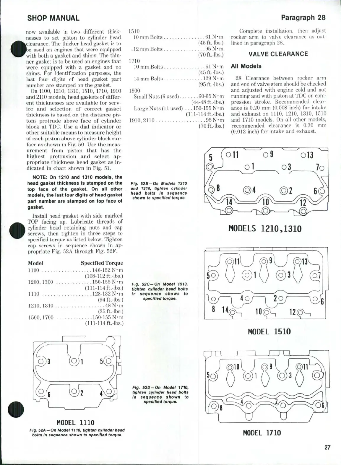
Fig. 52B-On Models
1210
and
1310,
tighten cylinder
head bolts
in
sequence
shown
to
specified torque.
MODELS 1210,1310
Fig. 52C-On Model
1510,
tighten cylinder head bolts
In sequence shown
to
specified torque.
MODEL
1510
Fig. 52D-On Modei
1710,
tighten cylinder head bolts
in sequence shown
to
specified torque.
MODEL
1710
27
 Loading...
