Paragraph 33
FORD
Fig.
56 —Drawing
of engine timing gears typical
of
1210
and
1310
models. Vaive timing Is correct
when timing marks (A and B) are aligned as
shown.
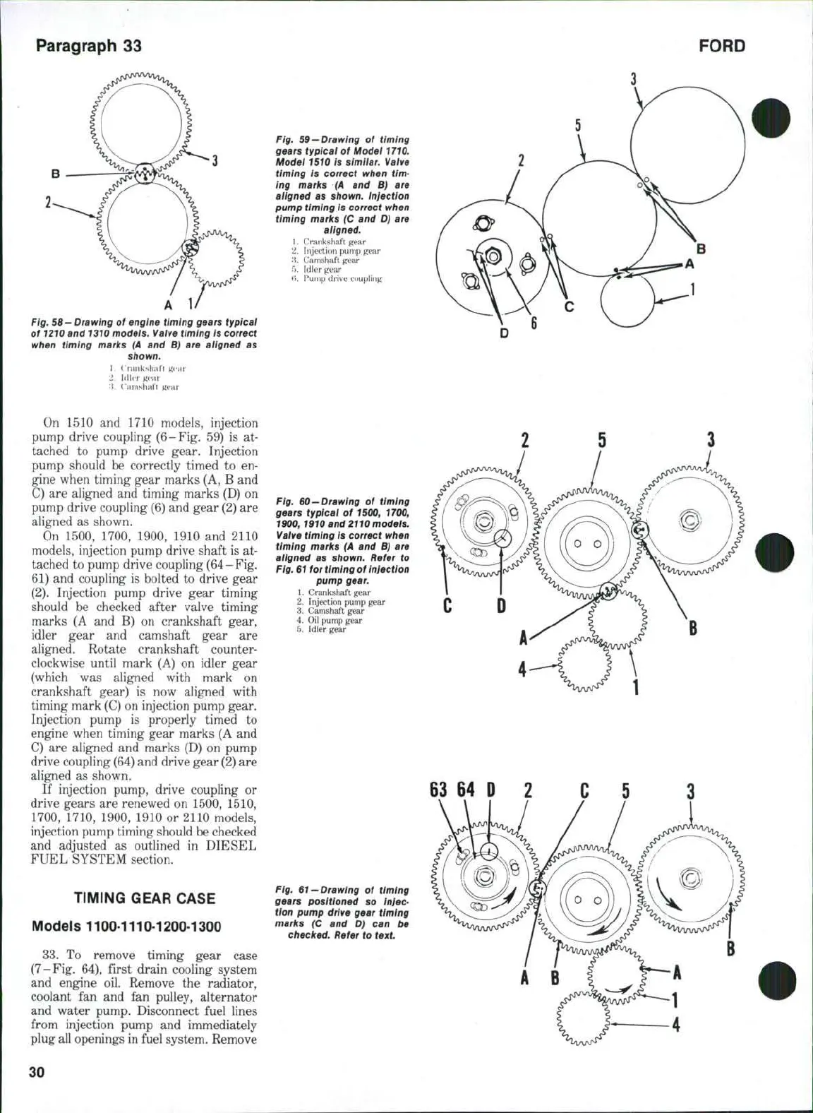
Fig. 59—Drawing of timing
gears typical of Model 1710.
Model 1510 is simiiar. Valve
timing is correct when tim-
ing marks (A and B) are
aligned as shown. Injection
pump timing is correct when
timing marks (C and D) are
aligned.
1.
Crankshaft gear
2.
Injecti(»n pump gear
'i.
Camshaft gear
5.
Idler gear
(i.
F'ump drive coupling
1.
(rank sha It
2.
UWvr
i^cai
:J.
I amslialt ^
On 1510 and 1710 models, injection
pump drive coupling (6-Fig. 59) is at-
tached to pump drive gear. Injection
pump should be correctly timed to en-
gine when timing gear marks (A, B and
C) are aligned and timing marks (D) on
pump drive coupling (6) and gear (2) are
aligned as shown.
On 1500, 1700, 1900, 1910 and 2110
models, injection pump drive shaft is at-
tached to pump drive coupling
(64
- Fig.
61) and coupling is bolted to drive gear
(2).
Injection pump drive gear timing
should be checked after valve timing
marks (A and B) on crankshaft gear,
idler gear and camshaft gear are
aligned. Rotate crankshaft counter-
clockwise until mark (A) on idler gear
(which was aligned with mark on
crankshaft gear) is now aligned with
timing mark (C) on injection pump gear.
Injection pump is properly timed to
engine when timing gear marks (A and
C) are aligned and marks (D) on pump
drive coupling
(64)
and drive gear
(2)
are
aligned as shown.
If injection pump, drive coupling or
drive gears are renewed on 1500, 1510,
1700,
1710, 1900, 1910 or 2110 models,
injection pump timing should be checked
and adjusted as outlined in DIESEL
FUEL SYSTEM section.
TIMING GEAR CASE
Models 1100-1110-1200-1300
33.
To remove timing gear case
(7-Fig, 64), first drain cooling system
and engine oil. Remove the radiator,
coolant fan and fan pulley, alternator
and water pump. Disconnect fuel lines
from injection pump and immediately
plug all openings in fuel system. Remove
Fig. 60—Drawing of timing
gears typieai of 1500, 1700,
1900,
1910
and
2110
models.
Valve timing is correct when
timing marks (A and B) are
aligned as shown. Refer to
Fig. 61 for timing of Injection
pump gear.
1.
Crankshaft gear
2.
Injection pump gear
3.
Camshaft gear
4.
Oil pump gear
5.
Idler gear
63
64 D 2
Fig.
61 —Drawing
of timing
gears positioned so injec-
tion pump drive gear timing
marks (C and D) can be
checked. Refer to text
30
 Loading...
