EasyManua.ls Logo

Ford 1100 User Manual

Ford 1100
58 pages
To Next Page IconTo Next Page
To Previous Page IconTo Previous Page
Page #3 background imageLoading...
Page #3 background image
1100,
1200
FINALDRIVE
152
FRONT AXLE AND STEERING
Axle
(2
Wheel Drive)
1
Axle
(4
Wheel Drive)
3
Manual Steering Gear
15
Power Steering
HYDRAULIC SYSTEM
Adjustments.
175
Control Valve
185
Filter
170
Lift Arm Housing
180
Pump
174
Testing
172
Trouble-Shooting
171
POWER TAKE-OFF
163
TRANSMISSION
Hydrostatic
Nonsynchromesh
105
Synchromesh
INDEX (CONT.)
1110,
1210
152
1
8
15
175
185
170
180
174
173
171
1300
154
1
8
15
20
175
185
170
180
174
173
171
1300,
1500
154
1
3
15
175
185
170
180
174
172
171
1510,
1710
154,
156
1
8
15
20
175
185
170
180
174
172,
173
171
1700,
1900
158
1
3
15
20
175
185
170
180
174
172
171
1910,
2110
158
1
8
15
20
175
185,187
170
180
174
173
171
163
110
105
165
120
130
165
120
165
120
130
166 166
123,
12(> 126
130
DUAL DIMENSIONS
This service manuai provides specifications in both the Metric (SI) and U.S. Customary systems of
measurement. The first specification is given in the measuring system used during manufacture, whiie the
second specification (given in parenthesis) is the converted measurement. For instance, a specification of
"0.28 mm (0.011 inch)" wouid indicate that the equipment was manufactured using the metric system of
measurement and the U.S. equivaient of 0.28 mm is 0.011
inch.
CONDENSED SERVICE DATA
1100
GENERAL
Engine Make
Engine Model LEK752C2
Number
of
Cylinders
2
Bore
75 mm
(2.95
in.)
Stroke
80 mm
(3.15
in.)
Displacement 706
cc
(43.1
cu. in.)
Compression Ratio
23:1
TUNE-UP
Firing Order
2-1
Valve Clearance-Cold
Intake
0.30 mm
(0.012
in.)
Exhaust
0.30 mm
(0.012
in.)
Valve Face Angle
Valve Seat Angle
Injection Timing,
Static-BTDC 23''-24°
Injector Opening Pressure 11760
kPa
(1705 psi)
1110 1200 1210
LEK757C
2
75 mm
(2.95
in.)
80 mm
(3.15
in.)
706
cc
(43.1 cu.
in.)
23:1
LEK802D
2
80 mm
(3.15
in.)
80 mm
(3.15
in.)
804
cc
(49.1
cu. in.)
23:1
S723
3
72
mm
(2.83
in.)
72
mm
(2.83
in.)
879
cc
(53.6 cu.
in.)
24:1
2-1
0.20 mm
(0.008
in.)
0.20
mm
(0.008
in.)
-45°
-45°
2-1
0.30 mm
(0.012
in.)
0.30 mm
(0.012
in.)
11760
kPa
(1705 psi)
11760
kPa
(1705 psi)
1-2-3
0.20
m m
(0.008 in.)
0.20
m m
(0.008 in.)
24°
11760 kPa
(1705 psi)
Question and Answer IconNeed help?

Do you have a question about the Ford 1100 and is the answer not in the manual?

Ford 1100 Specifications

General IconGeneral
Drive2WD
Fuel Capacity11.5 L
Gears6 forward, 2 reverse
CoolingLiquid
Fuel Tank Capacity11.5 L

Summary

Condensed Service Data

General

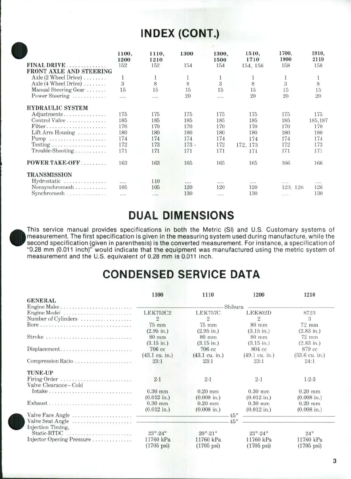
Engine make, model, cylinders, bore, stroke, displacement, compression ratio.

Tune-Up

Firing order, valve clearance, timing, pressure, speeds, power rating, battery specs.

Capacities

Cooling system, crankcase, fuel tank, transmission, axles, and differential capacities.

Special Torques

Torque specifications for connecting rods, main bearings, crankshaft, flywheel, cylinder head.

Front Axle and Steering System

Front Axle (Two Wheel Drive)

Details on front axle for two-wheel drive models, including components and adjustments.

Front Axle (Four Wheel Drive)

Information on the front axle assembly for four-wheel drive models.

Outer Drive Assembly

Procedure for removing and disassembling the outer drive assembly.

Bevel Drive Gears and Differential

Instructions for disassembling bevel drive gears and the differential unit.

Front Axle and Steering System (Cont.)

Differential Carrier Bearing Preload

Procedure for adjusting differential carrier bearing preload.

Ring Gear to Pinion Backlash

Instructions for checking and adjusting ring gear to pinion backlash.

Front Axle and Steering System (Cont.)

Remove and Reinstall

Steps for removing and reinstalling the front drive axle assembly.

Outer Drive Assembly

Procedure for removing the outer drive assembly unit.

Front Axle and Steering System (Cont.)

Bevel Drive Gears and Differential

Procedure for removing differential and bevel gears.

Front Axle and Steering System (Cont.)

Differential Carrier Bearing Preload

Procedure for adjusting carrier bearing preload.

Front Axle and Steering System (Cont.)

Ring Gear to Pinion Backlash

Procedure for adjusting ring gear to pinion backlash.

Manual Steering Gear

All Models So Equipped (Except 1710 Offset)

Description of manual steering gear and free play adjustment.

Overhaul

Procedure for disassembling and overhauling the steering gear.

Manual Steering Gear (Cont.)

Model 1710 Offset

Specifics for the 1710 Offset model's manual steering.

Overhaul

Procedure for overhauling the steering gear assembly.

Power Steering System

All Models So Equipped

Description of integral hydraulic power assist steering.

All Models So Equipped (Except 1710 Offset)

Details on power steering gear removal and adjustment.

Power Steering System (Cont.)

Relief Valve Pressure

Procedure for checking and adjusting power steering relief valve pressure.

Priority Flow Control Valve

All Models So Equipped

Function and service of the priority flow control valve.

Hydraulic Pump

All Models So Equipped

Information on hydraulic pump service and replacement.

Engine and Components

R&R Engine Assembly

Procedure for removing and reinstalling the engine assembly.

Cylinder Head

Steps for removing and reinstalling the cylinder head.

Engine and Components (Cont.)

Cylinder Head (Cont.)

Continued procedure for cylinder head service.

Valve Clearance

All Models

Procedure for checking and adjusting valve clearance.

Rocker Arms and Push Rods

All Models

Inspection and wear limits for rocker arms and push rods.

Valve Springs

All Models

Specifications for valve springs, including free length and test load.

Valves, Guides and Seats

All Models

Information on valve face angle, stem diameter, and seat specifications.

Valve Specifications

Valve Seat Width

Specifications for valve seat width across various models.

Stem Diameter

Specifications for valve stem diameter (intake and exhaust).

Valve Recession

Specifications for valve recession from cylinder head face.

Valve Timing

All Models

Procedure for checking and adjusting valve timing.

Timing Gear Case

Models 1100-1110-1200-1300

Procedure for removing and reinstalling the timing gear case.

Timing Gear Case (Cont.)

Models 1210-1310

Procedure for removing and reinstalling the timing gear case.

Models 1500-1510-1700-1900-1910-2110

Procedure for removing and reinstalling the timing gear case.

Camshaft and Cam Followers

Models 1100-1110-1200-1300

Procedure for removing and reinstalling the camshaft and cam followers.

Camshaft and Cam Followers (Cont.)

Models 1210-1310

Procedure for removing and reinstalling the camshaft and cam followers.

Models 1510-1710

Procedure for removing and reinstalling the camshaft and cam followers.

Camshaft and Cam Followers (Cont.)

Camshaft and Cam Followers (Cont.)

Models 1500-1700-1900-1910-2110

Procedure for removing and reinstalling the camshaft and cam followers.

Pistons, Rings and Cylinder

All Models

Information on pistons, rings, and cylinder service.

Pistons, Rings and Cylinder (Cont.)

Piston Specifications

Piston & Ring Dimensions

Specifications for piston diameter, bore, clearance, and ring gap.

Piston Pin

Models 1100-1110-1200-1300-1310-1900

Piston pin installation and clearance specifications.

Model 1210

Piston pin installation and clearance specifications.

Models 1910-2110

Piston pin installation and clearance specifications.

Connecting Rods and Bearings

All Models

Procedure for installing and sizing connecting rod crankpin bearings.

Crankshaft and Main Bearings

All Models

Procedure for removing and installing crankshaft and main bearings.

Crankshaft and Main Bearing Specifications

Main Journal & Bearing Specs

Specifications for crankshaft main journals and bearing clearances.

Crankpin Journal & Bearing Specs

Specifications for crankshaft crankpin journals and bearing clearances.

Crankshaft Specifications (Cont.)

Crankshaft Journal Diameter & Clearance

Specifications for crankshaft journal diameter and clearance.

Crankshaft End Play

Specifications for crankshaft end play.

Flywheel

All Models

Procedure for removing, installing, and torquing the flywheel.

Engine Balancer

Model 2110

Procedure for removing and disassembling the engine balancer assembly.

Oil Pump and Relief Valve

Models 1100-1110-1200-1300

Procedure for removing and servicing the oil pump assembly.

Models 1210-1310

Procedure for removing and servicing the oil pump assembly.

Oil Pump and Relief Valve (Cont.)

Models 1510-1710

Procedure for removing and servicing the oil pump assembly.

Models 1500-1700-1900-1910-2110

Procedure for removing and servicing the oil pump assembly.

Diesel Fuel System

Fuel Filter

Maintenance and replacement of the fuel filter.

Bleeding

Procedure for bleeding the fuel system after maintenance.

Diesel Fuel System (Cont.)

Injection Pump

Procedure for removing and reinstalling the injection pump.

Diesel Fuel System (Cont.)

Injection Pump

Procedure for removing and reinstalling the injection pump.

Pump Timing

Procedure for checking and adjusting injection pump timing.

Diesel Fuel System (Cont.)

Injection Pump

Procedure for checking and adjusting injection pump timing.

Pump Timing

Procedure for checking and adjusting injection pump timing.

Engine Speed Adjustment

Models 1100-1110-1200-1300

Procedure for adjusting engine idle and maximum speeds.

Models 1210-1310-1500-1510-1700-1710-1900-1910-2110

Procedure for adjusting engine idle and maximum speeds.

Governor

Models 1100-1110-1200-1300

Description of governor flyweights and linkage.

Models 1210-1310

Description of governor flyweights and linkage.

Model 1510

Description of governor flyweights and linkage.

Injector Nozzles

All Models

Procedure for testing and locating faulty injector nozzles.

Remove and Reinstall

Procedure for removing and reinstalling injector nozzles.

Testing

Procedure for testing injector nozzles.

Injector Nozzle Service Procedures

Specifications and Overhaul

Injector nozzle opening pressure, spray pattern, seat leakage, and overhaul.

Cooling System

Radiator

Information on radiator cap pressure and coolant.

Thermostat

Location and temperature specifications for the thermostat.

Water Pump (Models 1100-1110-1200-1300)

Procedure for removing and overhauling the water pump.

Cooling System (Cont.)

Water Pump (Models 1500-1510-1700-1910-2110)

Procedure for removing and overhauling the water pump.

Electrical System

Alternator and Regulator

Information on alternator and regulator types and precautions.

Alternator and Regulator (Cont.)

Overhaul

Procedure for overhauling the alternator assembly.

Safety Start Switch

Models 1100-1110-1200-1210-1300-1500-1700-1900

Function and adjustment of the safety start switch.

Models 1310-1510-1710-1910-2110

Description of the safety start system components.

Starting Motor and Solenoid

Models 1100-1110-1200-1210-1310-1510

Exploded view and clearance checks for starter and solenoid.

Starting Motor and Solenoid (Cont.)

Model 1300

Exploded view and specifications for starting motor.

Starting Motor and Solenoid (Cont.)

Models 1500-1700-1900-1910-2110

Starting motor specifications and checks.

Model 1710

Starting motor specifications and checks.

Engine Clutch Adjustment

All Models

Procedure for adjusting clutch pedal free travel.

Clutch Split

Procedure for separating the tractor for clutch housing access.

Related product manuals