Paragraphs 29-31
FORD
ROCKER ARMS AND PUSH
RODS
All Models
29.
A single rocker arm shaft
(10-Fig. 47 and 48) is used to support
all the rocker arms on 1210, 1310, 1510
and 1710 models. All other models use
an individual support bracket and shaft
(6-Fig. 45, 46 or 49) to separately sup-
port rocker arms of each cylinder. Note
that rocker arms and push rods should
be reinstalled in their original location if
being reused.
Inspect all parts for wear or damage.
Clearance between rocker shaft and
bore of rocker arm should not exceed
0.20 mm (0.008 inch). Measure shaft OD
and rocker arm ID and renew parts that
do not meet the following wear limits.
Model Wear Limit
1100-1110-1200-1300-1500-
1700-1900
Shaft
OD
13.55 mm
(0.534 in.)
Rocker Arm ID 13.72 mm
(0.540 in.)
1210-1310
Shaft
OD
11.57 mm
(0,456 in.)
Rocker Arm ID 11.73 mm
(0,462 in,)
1510-1710
Shaft
OD
17.55 mm
(0.691 in.)
Rocker Arm ID 17.83 mm
(0.702 in,)
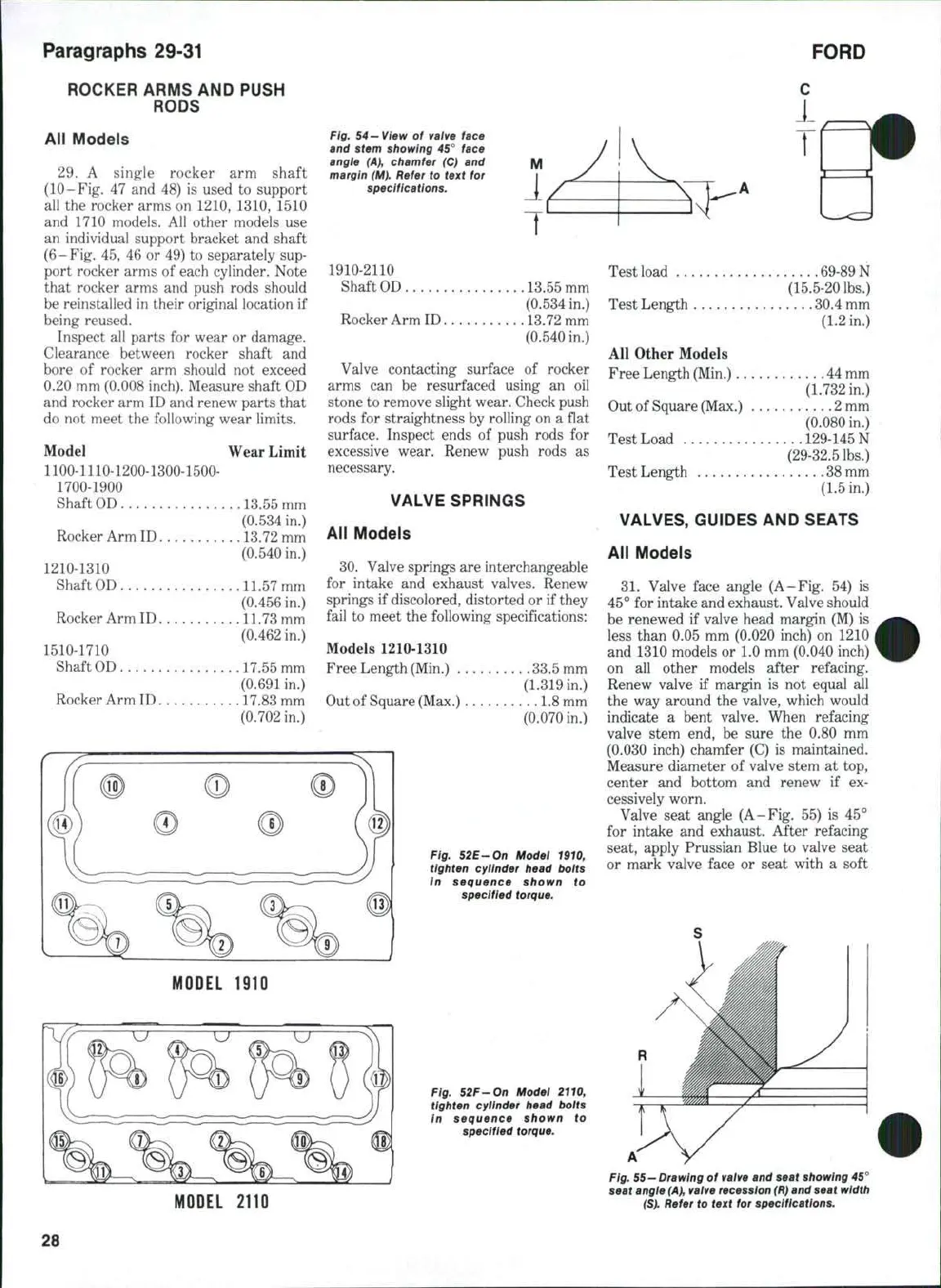
Fig. 54—View of valve face
and stem showing 45° face
angle (A), chamfer (C) and
margin (M). Refer to text for
specifications.
M
1910-2110
Shaft
OD
13,55 mm
(0.534 in.)
Rocker Arm ID 13.72 mm
(0.540 in.)
Valve contacting surface of rocker
arms can be resurfaced using an oil
stone to remove slight wear. Check push
rods for straightness by rolling on a flat
surface. Inspect ends of push rods for
excessive wear. Renew push rods as
necessary.
VALVE SPRINGS
All Models
30.
Valve springs are interchangeable
for intake and exhaust valves. Renew
springs if discolored, distorted or if they
fail to meet the following specifications:
Models 1210-1310
Free Length (Min,) 33,5 mm
(1.319 in.)
Out of Square (Max.) 1,8 mm
(0.070 in.)
Fig. 52E-On Model 1910,
tighten cylinder head bolts
in sequence shown to
specified torque.
MODEL
1910
Fig. 52F-On Model 2110,
tighten cylinder head bolts
In sequence shown to
specified torque.
Test load ,, 69-89N
(15.5-20 lbs.)
Test Length 30,4 mm
(1.2 in.)
All Other Models
Free Length (Min,) 44 mm
(1.732 in.)
Out of Square (Max,) 2 mm
(0,080 in.)
Test Load 129-145 N
(29-32,5 lbs,)
TestLength 38mm
(1.5 in.)
VALVES, GUIDES AND SEATS
All Models
31.
Valve face angle (A-Fig. 54) is
45° for intake and exhaust. Valve should
be renewed if valve head margin (M) is
less than 0.05 mm (0.020 inch) on 1210
and 1310 models or 1.0 mm (0,040 inch)
on all other models after refacing.
Renew valve if margin is not equal all
the way around the valve, which would
indicate a bent valve. When refacing
valve stem end, be sure the 0.80 mm
(0,030 inch) chamfer (C) is maintained.
Measure diameter of valve stem at top,
center and bottom and renew if ex-
cessively worn.
Valve seat angle (A-Fig, 55) is 45°
for intake and exhaust. After refacing
seat, apply Prussian Blue to valve seat
or mark valve face or seat with a soft
MODEL
2110
Fig.
55
—Drawing of
valve
and seat showing 45°
seat angle
(A),
valve recession
(R)
and seat width
(S).
Refer to text for specifications.
28
 Loading...


