SHOP MANUAL
Paragraph
4
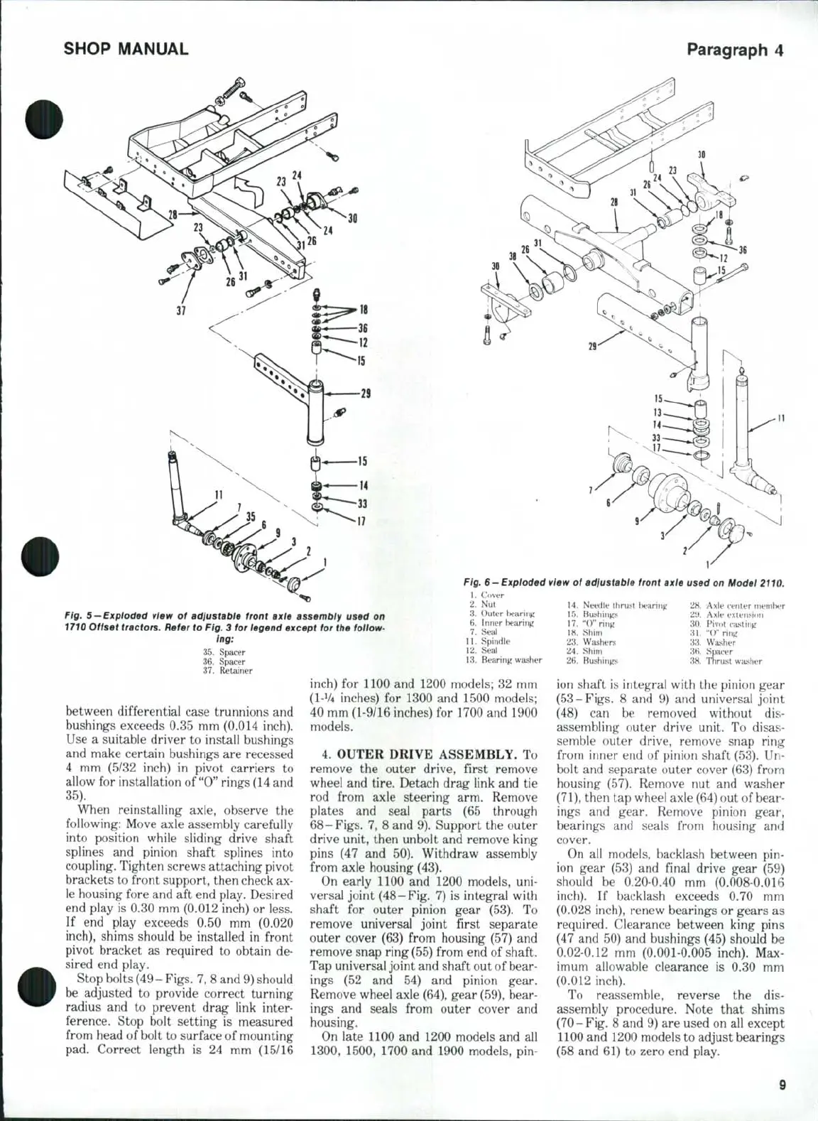
Fig.
5
- Exploded view of adiustabie front axie assembiy used on
1710 Offset tractors. Refer to
Fig.
3 for iegend except for the follow-
ing:
35.
Spacer
36.
Spacer
37.
Retainer
inch)
for
1100
and
1200 models;
82
mm
(I-V4 inches)
for
1300
and
1500 models;
between differential case trunnions and
Fig.
6
—Expioded
view of adiustable front axle used on Model 2110.
1.
Cover
2.
Nut 14.
Needle thrust l)earirig
28.
Axle tenter ?nemU?r
3.
Outer tearing
15.
Bushings
21>.
Axle extension
6. Injier hearing
17. "0"
ring
30.
Pivot casting
7.
Seal
18.
Shim
31. "()"
ring
11.
Spindle
23.
Washers
33.
Washer
12.
Seal
24.
Shim
3fi.
Spacer
13.
Bearing washer
2H.
Bushings
38.
Thrust washer
bushings exceeds 0.35 mm (0.014 inch).
Use
a
suitable driver
to
install bushings
and make certain bushings are recessed
4
mm (5/32
inch)
in
pivot carriers
to
allow
for
installation of
"0"
rings (14 and
35).
When reinstalling axle, observe
the
following: Move axle assembly carefully
into position while sliding drive shaft
splines
and
pinion shaft splines into
coupling. Tighten screws attaching pivot
brackets to front support, then check ax-
le housing fore and
aft
end play. Desired
end play
is
0.30 mm (0.012 inch)
or
less.
If
end
play exceeds
0.50 mm
(0.020
inch),
shims should
be
installed
in
front
pivot bracket
as
required
to
obtain
de-
sired end play.
Stop bolts
(49
-
Figs.
7, 8 and 9) should
be adjusted
to
provide correct turning
radius
and to
prevent drag link inter-
ference. Stop bolt setting
is
measured
from head of bolt to surface
of
mounting
pad. Correct length
is 24 mm
(15/16
40 mm (1-9/16 inches)
for
1700 and 1900
models.
4.
OUTER DRIVE ASSEMBLY.
To
remove
the
outer drive, first remove
wheel
and
tire. Detach drag link and
tie
rod from axle steering
arm.
Remove
plates
and
seal parts
(65
through
68-Figs.
7, 8
and 9). Support the outer
drive unit, then unbolt and remove king
pins
(47 and 50).
Withdraw assembly
from axle housing (43).
On early 1100
and
1200 models,
uni-
versal joint (48-Fig. 7)
is
integral with
shaft
for
outer pinion gear
(53). To
remove universal joint first separate
outer cover (63) from housing (57)
and
remove snap ring (55) from end
of
shaft.
Tap universal joint and shaft out of bear-
ings
(52 and 54) and
pinion gear.
Remove wheel axle (64), gear (59), bear-
ings
and
seals from outer cover
and
housing.
On late 1100 and 1200 models
and all
1300,
1500, 1700
and
1900 models,
pin-
ion shaft
is
integral with the pinion gear
(53-Figs.
8 and 9) and
universal joint
(48)
can be
removed without
dis-
assembling outer drive unit.
To
disas-
semble outer drive, remove snap ring
from inner end
of
pinion shaft (53).
Un-
bolt
and
separate outer cover (63) from
housing (57). Remove
nut and
washer
(71),
then tap wheel axle (64) out of bear-
ings
and
gear. Remove pinion gear,
bearings
and
seals from housing
and
cover.
On
all
models, backlash between
pin-
ion gear
(53) and
final drive gear
(59)
should
be
0.20-0.40
mm
(0.008-0.016
inch).
If
backlash exceeds
0.70 mm
(0.028 inch), renew bearings
or
gears
as
required. Clearance between king pins
(47
and
50)
and
bushings (45) should
be
0,02-0.12
mm
(0.001-0.005 inch).
Max-
imum allowable clearance
is 0.30 mm
(0.012 inch).
To reassemble, reverse
the dis-
assembly procedure. Note that shims
(70-Fig.
8
and 9) are used on all except
1100 and 1200 models to adjust bearings
(58 and 61)
to
zero end play.
9
 Loading...


