SHOP MANUAL
Paragraphs 55-56
Fig. 106-Exploded view of
gear type engine oil pump
assembly typical of 1500,
1700, 1900, 1910 and 2110
models.
1.
Oil transfer tube
2.
Oil pressure relief valve
3.
Drive gear
4.
End cover
5.
Pump gears
6. Pump housing
7.
Adapter tube
8. Pickup tube
Fig.
109—Use
a straightedge and feeler gage to
measure end clearance between face of pump
gears and machined surface housing. Refer to
text
Fig. 110—Measure clearance between gear
teeth and housing using a feeler gage as shown.
Refer to text
DIESEL FUEL SYSTEM
On 1100, 1110, 1200 and 1300 models,
the two pumping elements of fuel injec-
tion pump are operated by a camshaft
which is located in the timing gear case.
On 1210 and 1310 models, the three
pumping elements of the injection pump
are operated by lobes on the engine
valve train camshaft. The fuel injection
pump used on all other models is also a
multiple plunger pump, but the pump
camshaft is located in the injection pump
housing.
Because of extremely close tolerances
and precise requirements of all diesei
components, it is of utmost importance
that only clean fuel is used and careful
maintenance be practiced at all times.
Unless necessary special tools are avail-
able,
service on injectors and injection
pumps should be limited to removal, in-
stallation and exchange of complete
assemblies. It is impossible to recaii-
fFuel
Shut-Off
Valve
brate an injection pump or reset an in-
jector without proper specifications,
equipment and training.
FUEL FILTER
All IVIodeis
55.
Fuel filter life depends upon
careful maintenance as well as the hours
of operation. The necessity for careful
filling with clean fuel cannot be over-
stressed.
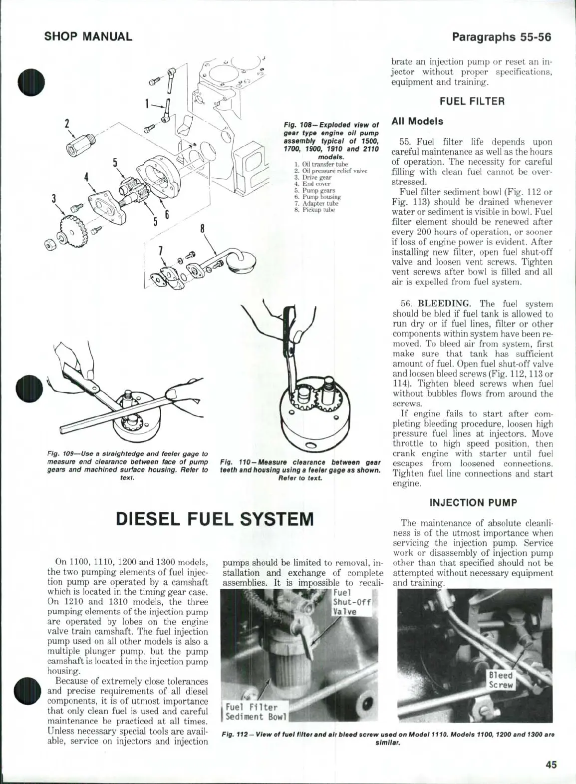
Fuel filter sediment bowl (Fig. 112 or
Fig. 113) should be drained whenever
water or sediment is visible in bowl. Fuel
filter element should be renewed after
every 200 hours of operation, or sooner
if loss of engine power is evident. After
installing new filter, open fuel shut-off
valve and loosen vent screws. Tighten
vent screws after bowl is filled and all
air is expelled from fuel system.
56,
BLEEDING. The fuel system
should be bled if fuel tank is allowed to
run dry or if fuel lines, filter or other
components within system have been re-
moved. To bleed air from system, first
make sure that tank has sufficient
amount of fuel. Open fuel shut-off valve
and loosen bleed screws (Fig, 112,
113
or
114).
Tighten bleed screws when fuei
without bubbles flows from around the
screws.
If engine fails to start after com-
pleting bleeding procedure, loosen high
pressure fuel lines at injectors. Move
throttle to high speed position, then
crank engine with starter until fuel
escapes from loosened connections.
Tighten fuel line connections and start
engine.
INJECTION PUMP
The maintenance of absolute cleanli-
ness is of the utmost importance when
servicing the injection pump. Service
work or disassembly of injection pump
other than that specified should not be
attempted without necessary equipment
and training.
I Fuel Fil t e r
I Sediment Bowl
Fig, 112- view of fuel filtm antf air bleed screw used on Model
1110,
Models 1100,1200 and
1300
are
[
I similar.
45
 Loading...


