Paragraphs 50-51
FORD
M
Fig.
105-Exploded view of
engine oil pump assembly
used on 1210 and 1310
1.
2.
3.
4.
5.
6.
7.
8.
9.
10.
11.
12.
13.
14.
15.
16.
17.
models.
Snap ring
Collar
Spring
Shaft
Shim
Cover
Inner rotor
Outer rotor
Pins
Spring
Idler gear
Thrust washer
Nut
Front plate
"0"
ring
Pickup tube
Strainer
Fig. 106-Oii pump shaft (2) and port block (1)
assembly Is a press fit In cyiinder biock on 1210
and 1310 models.
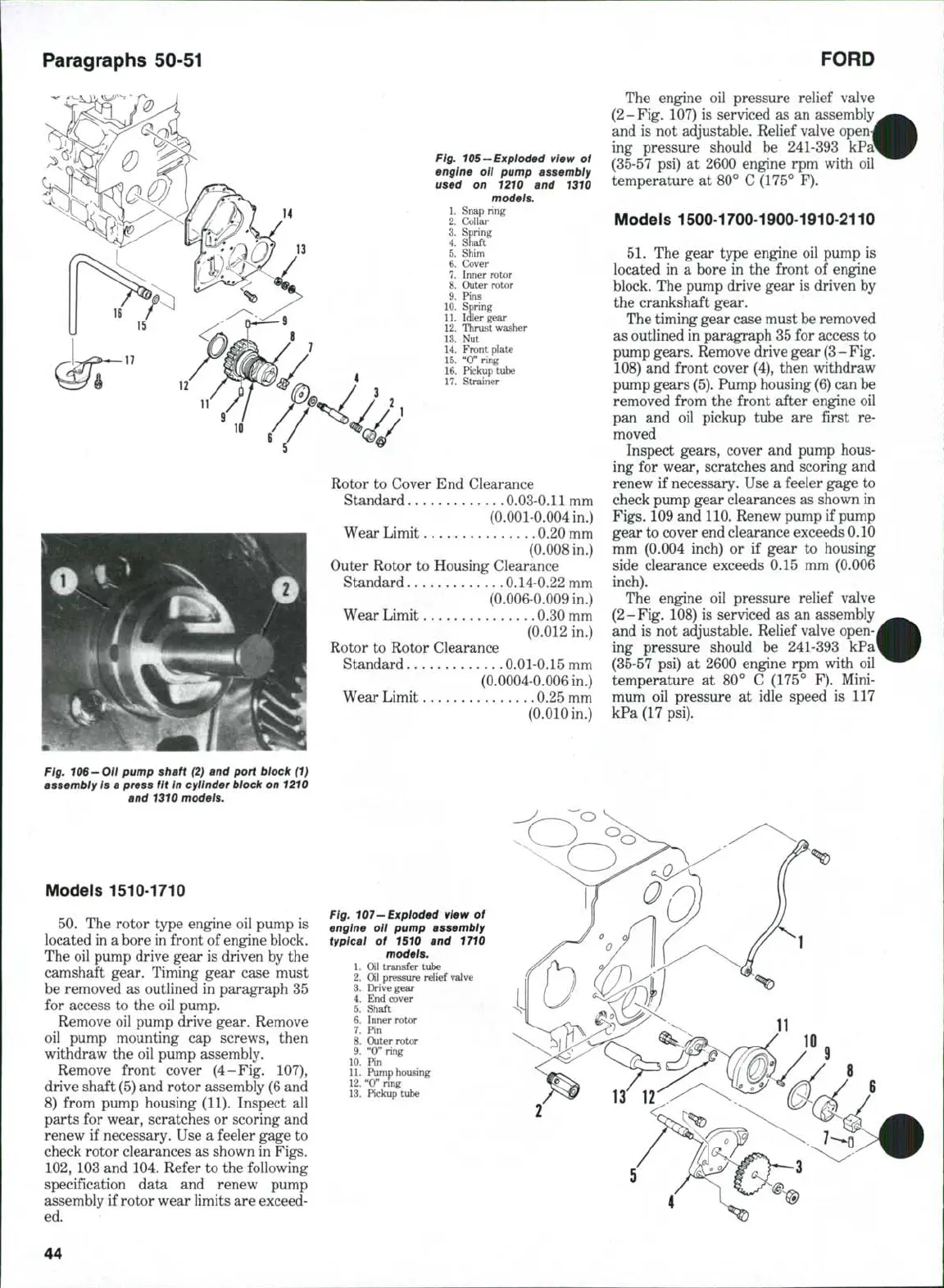
Models 1510-1710
50.
The rotor type engine oil pump is
located in a bore in front of engine block.
The oil pump drive gear is driven by the
camshaft gear. Timing gear case must
be removed as outlined in paragraph 35
for access to the oil pump.
Remove oil pump drive gear. Remove
oil pump mounting cap screws, then
withdraw the oil pump assembly.
Remove front cover (4-Fig, 107),
drive shaft (5) and rotor assembly (6 and
8) from pump housing (11). Inspect all
parts for wear, scratches or scoring and
renew if necessary. Use a feeler gage to
check rotor clearances as shown in Figs.
102,
103 and 104. Refer to the following
specification data and renew pump
assembly if rotor wear limits are exceed-
ed.
Rotor to Cover End Clearance
Standard 0.03-0,11 mm
(0,001-0,004 in.)
Wear Limit 0,20 mm
(0.008 in.)
Outer Rotor to Housing Clearance
Standard 0.14-0,22 mm
(0,006-0,009 in.)
Wear Limit 0,30 mm
(0.012 in,)
Rotor to Rotor Clearance
Standard 0.01-0.15 mm
(0,0004-0,006 in,)
Wear Limit 0.25 mm
(0.010 in.)
The engine oil pressure relief valve
(2-Fig, 107) is serviced as an assembly
and is not adjustable. Relief valve open
ing pressure should be 241-393
(35-57 psi) at 2600 engine rpm with oil
temperature at 80° C (175° F),
Models 1500-1700-1900-1910-2110
51.
The gear type engine oil pump is
located in a bore in the front of engine
block. The pump drive gear is driven by
the crankshaft gear.
The timing gear case must be removed
as outlined in paragraph 35 for access to
pump gears. Remove drive gear
(3
- Fig,
108) and front cover (4), then withdraw
pump gears
(5).
Pump housing
(6)
can be
removed from the front after engine oil
pan and oil pickup tube are first re-
moved
Inspect gears, cover and pump hous-
ing for wear, scratches and scoring and
renew if necessary. Use a feeler gage to
check pump gear clearances as shown in
Figs,
109 and^ 110. Renew pump if pump
gear to cover end clearance exceeds 0,10
mm (0,004 inch) or if gear to housing
side clearance exceeds 0.15 mm (0,006
inch).
The engine oil pressure relief vaJve
(2-Fig, 108) is serviced as an assembly
and is not adjustable. Relief valve open-
ing pressure should be 241-393 kPa'
(35-57 psi) at 2600 engine rpm with oil
temperature at 80° C (175° F). Mini-
mum oil pressure at idle speed is 117
kPa (17 psi).
Fig. 107-Exploded view of
engine oil pump assembly
typical of 1510 and 1710
models,
\. Oil transfer tube
2.
Oil pressure relief v^ve
3.
Drive gear
4.
End cover
5.
Shaft
6. Inner rotor
7.
Pin
8. Outer rotor
9. "0" ring
10.
Pin
11.
Pump housing
12.
"0"
nng
13.
Pickup tube
44
 Loading...


