Paragraphs 89-91
FORD
front of housing as shown at (A-Fig.
145).
Press impeller onto shaft until end
of shaft is flush with rear of impeller (B).
Support impeller and shaft surfaces (B),
then press hub onto shaft until flush
with front of shaft as shown at (C).
Installation of pump is reverse of
removal.
Models 1500-1510-1700-1710-
1900-1910-2110
89,
R&R AND OVERHAUL. To
remove water pump, first drain coolant
from radiator and cylinder block. Re-
move radiator as outlined in paragraph
85.
Loosen alternator mounting bolts,
then remove fan belt and fan. Remove
pump mounting bolts and remove water
pump assembly.
Remove mounting plate (3-Fig. 146).
Remove set screw (9) from housing.
Press shaft and bearing assembly
(8)
for-
ward out of impeller (5) and housing.
Press seal (6) rearward out of housing.
Press pump shaft out of pulley (10).
Fig.
144—Exploded
view of water pump assembiy
used on
1210
and
1310
modeis. Thermostat (2) is
located in pump housing (8).
1.
Spring
2.
Thermostat
3.
Gasket
4.
Mounting plate
5.
Gasket
6. Impeller
7. Seal assy.
8. Housing
9. Shaft
&
bearing assy.
10.
Hub
11.
Pulley
12.
Spacer
13.
Fan
B
Fig,
145 —Cross
section of water pump used on
1210 and 1310 modeis. Refer to text for
assembly dimensions (A, B and C) and to Fig,
144 for iegend.
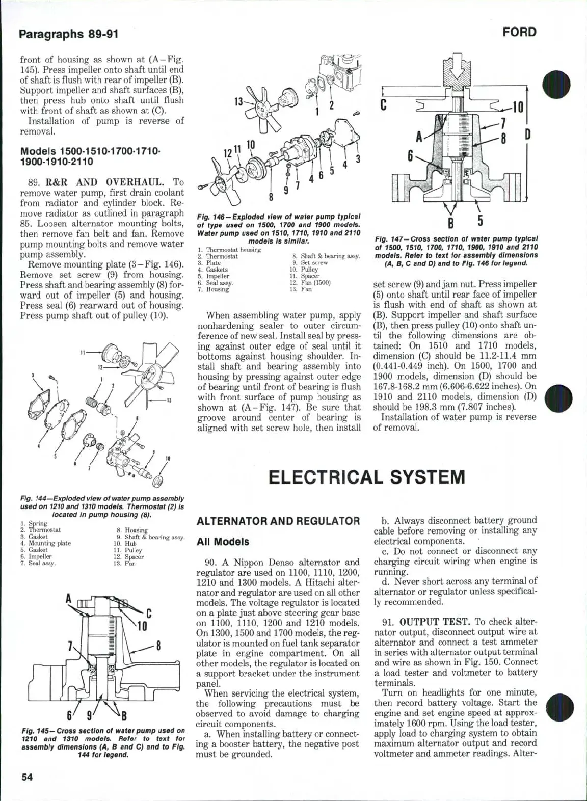
Fig, 146-Exploded view of water pump typicai
of type used on 1500, 1700 and 1900 modeis.
Water pump used on 1510, 1710, 1910 and 2110
models is
simiiar.
1.
Thermostat housing
2.
Thermostat 8. Shaft
&
bearing assy.
3.
Plate 9. Set screw
4.
Gaskets 10. Puliey
5.
Impeller 11. Sfwicer
6. Seal assy. 12. Fan (1500)
7.
Housing 13. ?"an
When assembling water pump, apply
nonhardening sealer to outer circum-
ference of new seal. Install seal by press-
ing against outer edge of seal until it
bottoms against housing shoulder. In-
stall shaft and bearing assembly into
housing by pressing against outer edge
of bearing until front of bearing is flush
with front surface of pump housing as
shown at (A-Fig. 147). Be sure that
groove around center of bearing is
aligned with set screw hole, then install
B
5
Fig, 147-
Cross
section of water pump typicai
of 1500, 1510, 1700, 1710, 1900, 1910 and 2110
modeis. Refer to text for assembly dimensions
(A,
B, C and D) and to Fig, 146 for iegend,
set screw (9) and jam nut. Press impeller
(5) onto shaft until rear face of impeller
is flush with end of shaft as shown at
(B).
Support impeller and shaft surface
(B),
then press pulley (10) onto shaft un-
til the following dimensions are ob-
tained: On 1510 and 1710 models,
dimension (C) should be 11.2-11.4 mm
(0.441-0.449 inch). On 1500, 1700 and
1900 models, dimension (D) should be
167.8-168.2 mm (6.606-6.622 inches). On
1910 and 2110 models, dimension (D)
should be 198,3 mm (7.807 inches).
Installation of water pump is reverse
of removal.
ELECTRICAL SYSTEM
ALTERNATOR AND REGULATOR
All Models
90.
A Nippon Denso alternator and
regulator are used on 1100, 1110, 1200,
1210 and 1300 models. A Hitachi alter-
nator and regulator are used on all other
models. The voltage regulator is located
on a plate just above steering gear base
on 1100, 1110, 1200 and 1210 models.
On 1300,1500 and 1700 models, the reg-
ulator is mounted on fuel tank separator
plate in engine compartment. On all
other models, the regulator is located on
a support bracket under the instrument
panel.
When servicing the electrical system,
the following precautions must be
observed to avoid damage to charging
circuit components.
a. When installing battery or connect-
ing a booster battery, the negative post
must be grounded.
b.
Always disconnect battery ground
cable before removing or installing any
electrical components.
c. Do not connect or disconnect any
charging circuit wiring when engine is
running,
d. Never short across any terminal of
alternator or regulator unless specifical-
ly recommended.
91.
OUTPUT TEST. To check alter-
nator output, disconnect output wire at
alternator and connect a test ammeter
in series with alternator output terminal
and wire as shown in Fig. 150, Connect
a load tester and voltmeter to battery
terminals.
Turn on headlights for one minute,
then record battery voltage. Start the
engine and set engine speed at approx-
imately 1600 rpm. Using the load tester,
apply load to charging system to obtain
maximum alternator output and record
voltmeter and ammeter readings. Alter-
54
 Loading...


