SHOP MANUAL
Paragraph 43
Model ldOO
Piston Diameter*
Standard 84,855-84.887 mm
(3.341-3.342 in.)
Minimum 84.70 mm
(3,335 in.)
Cylinder Bore
Standard 85,00-85.035 mm
(3,3465-3.3478 in.)
Maximum 86.2 mm
(3.394 in.)
Piston to Cylinder Clearance
Desired 0.115-0.180 mm
(0,0045-0.0070 in,)
Maximum 0.30 mm
(0,012 in.)
Piston Pin Bore
Standard 24.999-25.003 mm
(0.9842-0.9844 in.)
Piston Ring End Gap
All Rings 0.20-0.45 mm
(0.008-0.018 in.)
Models 1910-2110
Piston Diameter*
Standard 84.88-84.91 mm
(3.342-3,343 in.)
Minimum 84.72 mm
(3,335 in.)
Cylinder Bore
Standard 85,00-85,022 mm
(3.3465-3.3475 in.)
Maximum 85.18 mm
(3.354 in.)
Piston to Cylinder Clearance
Desired 0.087-0.139 mm
(0.0035-0.0055 in.)
Maximum 0.30 mm
(0.012 in.)
Piston Pin Bore
Standard 32.0 mm
(1.260 in.)
Maximum 32.08 mm
(1,263 in.)
Piston Ring End Gap
All Rings 0.20-0,40 mm
(0.008-0.016 in.)
* Measure piston diameter at bottom of
the skirt at right angle to piston pin
bore.
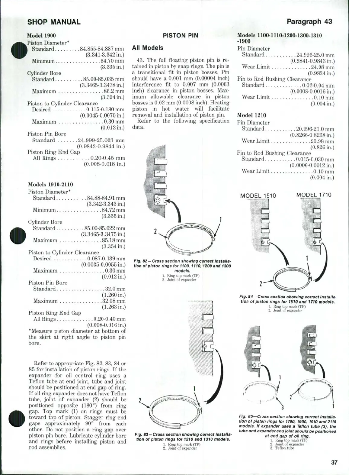
Refer to appropriate Fig. 82, 83, 84 or
85 for installation of piston rings. If the
expander for oil control ring uses a
Teflon tube at end joint, tube and joint
should be positioned at end gap of ring.
If
oil
ring expander does not have Teflon
tube,
joint of expander (2) should be
positioned opposite (180°) from ring
gap.
Top mark (1) on rings must be
toward top of piston. Stagger ring end
gaps approximately 90° from each
other. Do not position a ring gap over
piston pin bore. Lubricate cylinder bore
and rings before installing piston and
rod assemblies.
PISTON PIN !
All Models
43.
The full floating piston pin is re-
tained in piston by snap rings, T"he pin is
a transitional fit in piston bosses. Pin
should have a 0.001 mm (0,00004 inch)
interference fit to
0.007
mm (0,0003
inch) clearance in piston bosses. Max-
imum allowable clearance in piston
bosses is 0.02 mm (0.0008
inch).
Heating
piston in hot water will facilitate
removal and installation of piston pin.
Refer to the following specification
data.
Fig. 62—
Cross section showing correct
Installa-
tion of piston rings for 1100,1110,1200 and
1300
modeis.
1.
Ring tx)p mark (TP)
2.
Joint of expander
Models 1100-1110-1200-1300-1310
-1900
Pin Diameter
Standard 24.996-25.0 mm
(0.9841-0.9843 in,)
Wear Limit 24.98 mm
(0.9834 in.)
Pin to Rod Bushing Clearance
Standard 0,02-0.04 mm
(0.0008-0.0016 in.)
Wear Limit 0.10 mm
(0,004 in.)
Model 1210
Pin Diameter
Standard 20.996-21.0 mm
(0,8266-0,8268 in,)
Wear Limit 20,98 mm
(0.826 in.)
Pin to Rod Bushing Clearance
Standard 0.015-0.030 mm
(0.0006-0.0012 in.)
Wear Limit 0.10 mm
(0,004 in.)
MODEL 1710
2
Fig.
64
—
Cross section showing correct Installa-
tion of piston rings for 1510 and 1710 models.
1.
Ring top mark (TP)
2.
Joint of expander
Fig.
63—Cross section showing correct
Installa-
tion of piston rings for 1210 and 1310 models.
1.
Ring top mark (TP)
2.
Joint of expander
Fig. 65—Cross section showing correct installa-
tion of piston rings for
1700,
1900,
1910
and
2110
models. If expander uses a Teflon tube (3), the
tube and expander end joint should be positioned
at end gap of oil ring.
1.
Ring top mark (TP)
2.
Joint of expander
3.
Teflon tube
37
 Loading...


