SHOP MANUAL
Paragraph 32
lead pencil. Install valve and rotate
valve against seat while applying light
Tessure against the valve. Seat contact
lint should be in center of valve face
and seat width should be within speci-
fied limits. If necessary, use a 30° stone
to lower seat contact point and use a 60°
stone to raise seat contact point. Both
stones will narrow the seat width. Check
for correct recession (R) of valve head
below machined surface of cylinder
head. Renewable valve seat inserts are
available on 1110, 1510, 1710, 1900,
1910 and 2110 models.
Measure valve stem diameter and
valve guide bore to determine stem to
guide clearance. Renewable valve guides
are used on 1910 and 2110 models. On
all other models, cylinder head must be
renewed if guides are excessively worn.
When installing new guides on 1910 and
2110 models, press guides in from the
top until upper end of guide is flush with
valve cover mounting surface of cylinder
head as shown in Fig. 56.
Check valves and seats against the
following specifications:
Valve Seat Width
Models 1100-1200-1300
Standard
1,2-1.5
mm
(0.047-0.059 in.)
Maximum 2.5 mm
(0.100 in.)
Models 1910-2110
Standard
1.7-2.5
mm
(0067-0.098 in.)
Maximum 3.0 mm
(0,120 in.)
All Other Models
Standard
1,2-1.5
mm
(0.047-0.059 in.)
Maximum 2.0 mm
(0,080 in.)
Stem Diameter-Intake
Models 1210-1310
Standard 6.955-6.97 mm
(0.2738-0.2744 in.)
Minimum ; 6.89 mm
(0.271 in.)
All Other Models
Standard 7,955-7,97 mm
(0.313-0.314 in.)
Minimum 7.88 mm
(0.310 in.)
Stem Diameter-Exhaust
Models 1210-1310
Standard 6.95-6.96 mm
(0,2736-0.2740 in.)
Minimum 6.84 mm
(0.269 in.)
All Other Models
Standard 7.95-7.96 mm
(0.313-0.314 in.)
Minimum 7.85 mm
(0.309 in.)
Stem to Guide Clearance-Intake
Models 1910-2110
Standard 0.06-0.085 mm
(0.0025-0,0035 in.)
Maximum 0.20 mm
(0.008 in.)
All Other Models
Standard 0.03-0.06 mm
(0.001-0.0025 in.)
Maximum 0.20 mm
(0.008 in.)
Stem to Guide Clearance-Exhaust
Models 1910-2110
Standard 0.06-0.85 mm
(0.0025-0.0035 in.)
Maximum 0.25 mm
(0.010 in.)
All Other Models
Standard 0.04-0.065 mm
(0.0015-0,0025 in.)
Maximum 0.25 mm
(0,010 in.)
Valve Recession From
Face of Cylinder Head
Models 1100-1110-1200-1300
Standard
1.2-1.5
mm
(0.047-0,059 in.)
Maximum 2.5 mm
(0.100 in.)
Models 1210-1310
Standard 0.85-1.15 mm
(0.0335-0.0455 in.)
Maximum 2.15 mm
(0.085 in,)
Models 1500-1700-1900
Standard
0,7-1.0
mm
(0,028-0.039 in.)
Maximum 2.0 mm
(0.080 in.)
Model 1510
Standard
0.8-1.1
mm
(0031-0.043 in.)
Maximum 1.8 mm
(0,070 in,)
Model 1710
Standard
1,05-1,35
mm
(0.041-0.053 in.)
Maximum 2.0 mm
(0,080 in.)
Model 1910
Standard
1.0-1.2
mm
(0.039-0.047 in.)
Maximum 2.0 mm
(0,080 in.)
Model 2110
Standard. 0.07-l.Omm
(0.028-0.039 in.)
Maximum 2,0 mm
(0,080 in.)
VALVE TIMING
All Models
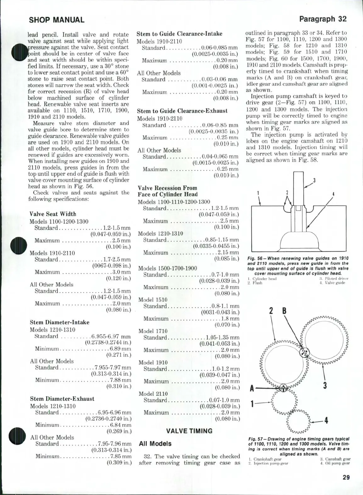
32,
The valve timing can be checked
after removing timing gear case as
outlined in paragraph 33 or 34, Refer to
Fig. 57 for 1100, 1110, 1200 and 1300
models; Fig, 58 for 1210 and 1310
models; Fig. 59 for 1510 and 1710
models; Fig. 60 for 1500, 1700, 1900,
1910 and 2110 models. Camshaft is prop-
erly timed to crankshaft when timing
marks (A and B) on crankshaft gear,
idler gear and camshaft gear are aligned
as shown.
Injection pump camshaft is keyed to
drive gear (2-Fig. 57) on 1100, 1110,
1200 and 1300 models. The injection
pump will be correctly timed to engine
when timing gear marks are aligned as
shown in Fig. 57.
The injection pump is activated by
lobes on the engine camshaft on 1210
and 1310 models. Injection timing will
be correct when timing gear marks are
aligned as shown in Fig. 58.
Fig. 56—When renewing vaive guides on 1910
and 2110 models, press new guide in from the
top until upper end of guide is fiush with vaive
cover mounting surface of cyiinder
head.
1.
Cylinder head A. Fil(>te<l driver
2.
Flush 4. Valve Kuide
Fig.
57—Drawing
of engine timing gears typical
of
1100,
1110, 1200 and 1300 models. Valve tim-
ing is correct when timing marks
(A
and
B)
are
aligned as shown.
1.
Crankshaft gear 3. Camshaft gear
2.
Injection pump gear 4. Oil pump gtar
29
 Loading...


