Paragraphs 2-3
FORD
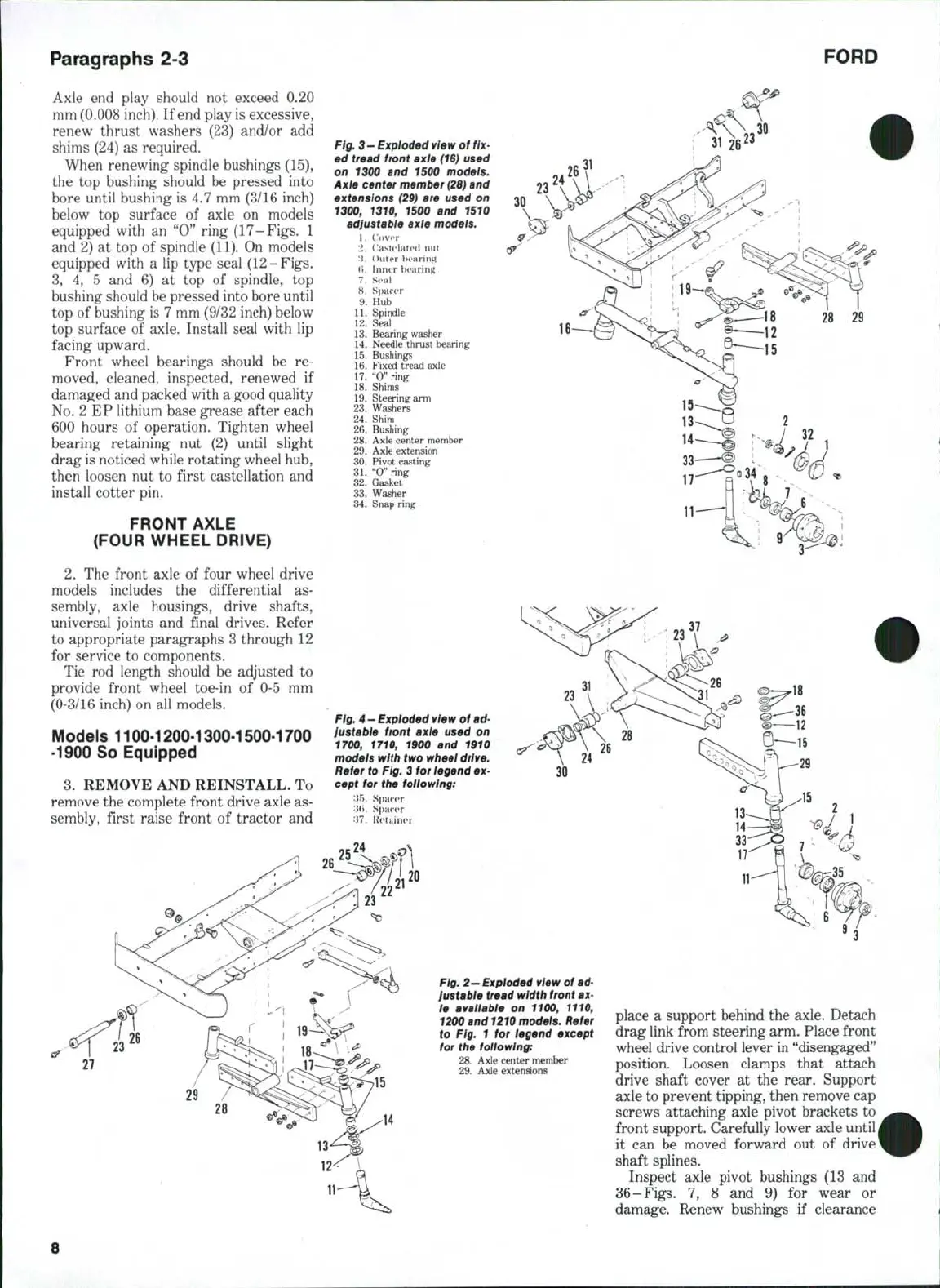
Axle end play should not exceed 0.20
mm (0.008 inch). If end play is excessive,
renew thrust washers (23) and/or add
shims (24) as required.
When renewing spindle bushings (15),
the top bushing should be pressed into
bore until bushing is 4.7 mm (3/16 inch)
below top surface of axle on models
equipped with an "0" ring (17-Figs, 1
and 2) at top of spindle (11). On models
equipped with a lip type seal (12-Figs.
3,
4, 5 and 6) at top of spindle, top
bushing should be pressed into bore until
top of bushing is 7 mm (9/32 inch) below
top surface of axle. Install seal with lip
facing upward.
Front wheel bearings should be re-
moved, cleaned, inspected, renewed if
damaged and packed with a good quality
No.
2 EP lithium base grease after each
600 hours of operation. Tighten wheel
bearing retaining nut (2) until slight
drag is noticed while rotating wheel hub,
then loosen nut to first castellation and
install cotter pin.
FRONT AXLE
(FOUR WHEEL DRIVE)
2.
The front axle of four wheel drive
models includes the differential as-
sembly, axle housings, drive shafts,
universal joints and final drives. Refer
to appropriate paragraphs 3 through 12
for service to components.
Tie rod length should be adjusted to
provide front wheel toe-in of 0-5 mm
(0-3/16 inch) on all models.
Models 1100-1200-1300-1500-1700
-1900 So Equipped
3.
REMOVE AND REINSTALL. To
remove the complete front drive axle as-
sembly, first raise front of tractor and
Fig.
3-Exploded view of
fix-
ed tread front axle
(16)
used
an 1300 and 1500 models.
Axle center member
(2S)
and
extensions (29} are used on
1300, 1310, 1500 and 1510
adiustable axie modeis.
1.
Cover
2.
llastelatcd
nut
:i.
Outer b(»aring
(i.
Inner iH'aring
7.
Seal
8.
Spacer
9.
Hub
11.
Spindle
12.
Seal
13.
Bearing washer
14.
Needle thrust bearing
15.
Bushings
16.
Fixed tread axle
17.
"0"
ring
18.
Shims
19.
Steering
arm
23.
Washers
24.
Shim
26.
Bushing
28.
Axle center member
29.
Axle extension
30.
Pivot casting
31.
"0"
ring
32.
Gasket
33.
Washer
34.
Snap ring
30
37
18
Ftg.
4 —
Expioded view of
ad-
iustabie front axle used on
1700, 1710, 1900 and 1910
models with two wheei drive.
Refer to
Fig.
3 for iegend
ex-
cept for the foiiowing:
'•\^y.
Spacer
'•\i\.
Spacer
'M. Retainer
Fig.
2-Exploded view of
ad-
iustabie tread width
front
ax-
le avaliabie on 1100, 1110,
1200
and
1210
models. Refer
to Fig. 1 for legend except
for the foltowtng:
28.
Axle center member
29.
Axle extensions
place a support behind the axle. Detach
drag link from steering arm. Place front
wheel drive control lever in "disengaged"
position. Loosen clamps that attach
drive shaft cover at the rear. Support
axle to prevent tipping, then remove cap
screws attaching axle pivot brackets to
front support. Carefully lower axle until
it can be moved forward out of drive
shaft splines.
Inspect axle pivot bushings (13 and
36-Figs. 7, 8 and 9) for wear or
damage. Renew bushings if clearance
 Loading...


