FP4000 Rev0204
13
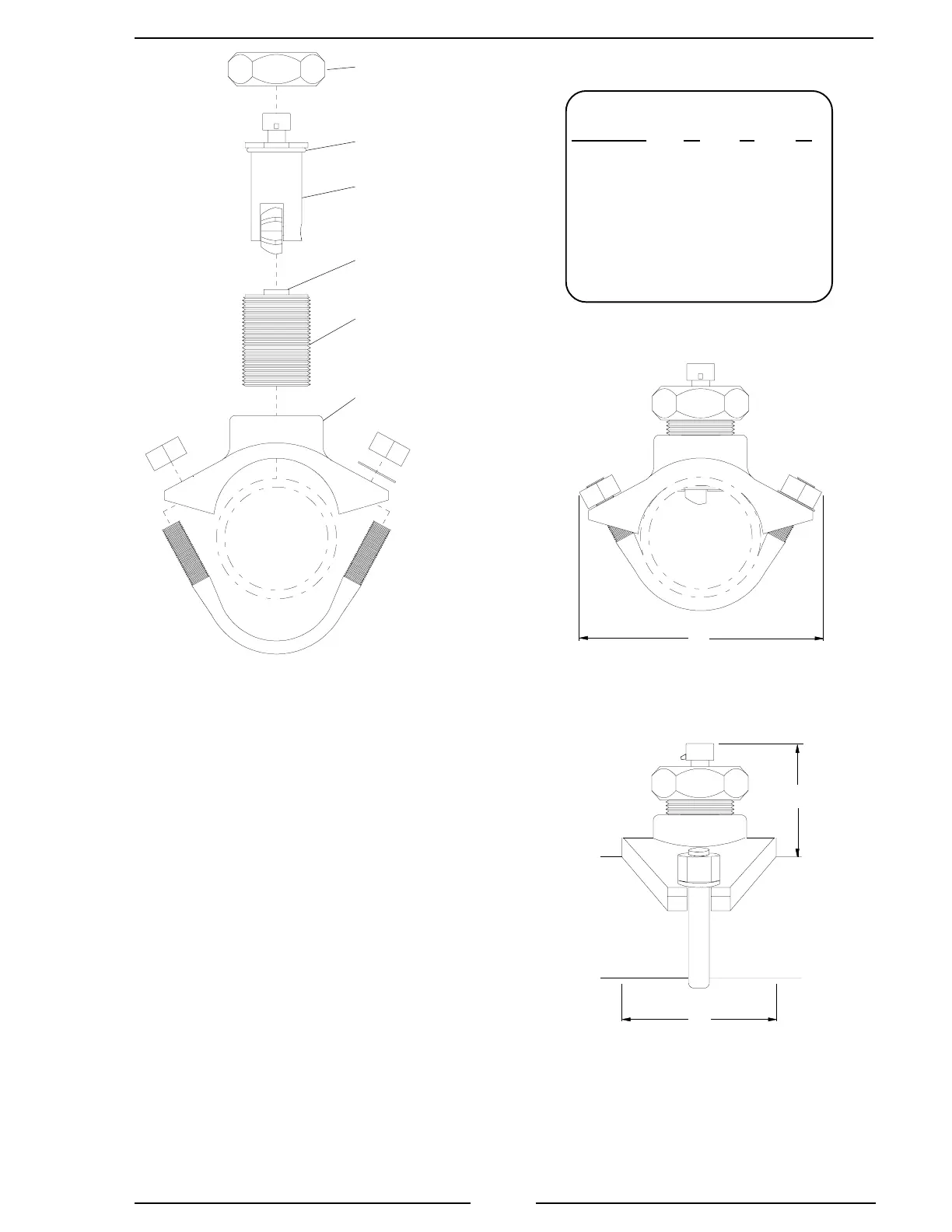
Figure 4. Saddle Clamp Installation
Note: These dimensions are
typical and are given to be used as
an aid in determining mounting
locations for flow sensors.
Note: Allow a minimum of 2
inches clearance at the sensor
top for removal/installation
of the connector.
Sensor
Housing
Paddlewheel
Flow Sensor
Retainer Cap
Saddle
Clamp
Alignment
Tab
O-Ring
Pipe Size Dimensions
(Sch 40) A B C
2 5.5 3.9 2.9
2.5 5.5 3.9 2.8
3 5.9 3.9 2.8
3.5 6.8 4.3 2.8
4 6.8 4.3 2.8
5 8 4.3 2.8
Measurements are in inches.
Note: When the retainer cap is
tightened make sure the sensor
rim flat spot does not disengage
from the alignment tab and
allow the flow sensor to rotate.
A
B
C

 Loading...
