EasyManua.ls Logo

FRC Insight Ultimate Series User Manual

FRC Insight Ultimate Series
35 pages
To Next Page IconTo Next Page
To Previous Page IconTo Previous Page
Page #20 background imageLoading...
Page #20 background image
FP4000 Rev0204
20
Program Features
See Programming section for more detailed information.
High and Low Flow Warning (Codes 315 and 316)
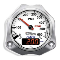
When the flow rate is above the programmed high flow value a flashing -HI- will
show in the digital display. When the flow rate is below the programmed low flow
value a flashing -LO- will show in the digital display.
Flow Cutoff (Codes 318 or 319)
The digital display will show 0 when the flow rate goes below the programmed
flow cutoff value.
External Totalizing Button (Optional)
The totalizing button is used to perform two functions, display total flow for a
discharge and reset the totalized flow to 0 if the totalizer reset function is set to YES.
Display Total Flow
When the totalizing button is pressed and released the digital display will show the
total accumulated flow. (The flow will be x 100 the number shown in the display.)
Press and release the button again to show normal flow rate.
Reset Total Flow to 0
The totalizer reset function (code 317) has two program settings YES or no. (Refer
to Programming Section). To enable the reset function the program totalizer reset is set
to YES.
Totalized flow will reset and start from 0 when power is applied to the control
module. Flow total can be reset to 0 during operations by displaying the total flow and
then pressing and holding the totalizing button until the display shows 0.
Question and Answer IconNeed help?

Do you have a question about the FRC Insight Ultimate Series and is the answer not in the manual?

FRC Insight Ultimate Series Specifications

General IconGeneral
BrandFRC
ModelInsight Ultimate Series
CategoryMeasuring Instruments
LanguageEnglish

Summary

Controls and Indicators Overview

INSIGHT ULTIMATE Installation Guide

Install Display Module

Provides instructions for mounting the display module, including panel cutout dimensions.

Flow Sensor Installation and Location

Flow Sensor Location Guidelines

Emphasizes critical placement for accurate flow rate measurement and laminar flow.

Saddle Clamp Flow Sensor Installation

Saddle Clamp Installation Steps

Step-by-step guide for installing the flow sensor using a saddle clamp.

Weldment Flow Sensor Installation

Weldment Installation Steps

Step-by-step guide for installing the flow sensor using a weldment.

Pressure Transducer Installation

Install Pressure Transducer

Instructions for mounting the pressure transducer, with cautions on tightening.

INSIGHT ULTIMATE Program Features

Flow Warnings and Cutoffs Configuration

Explains high/low flow warnings and flow cutoff functionalities.

INSIGHT ULTIMATE Programming

Program Access Mode Operations

Entering and Changing Program Codes

Steps for entering three-digit codes and modifying settings.

INSIGHT ULTIMATE Program Code Details

More Program Code Configurations

Calibration Codes and Error Handling

INSIGHT ULTIMATE Calibration Procedures

Single Point Flow Calibration

Detailed steps for single-point flow calibration using magnet sensors.

Multiple Point Flow Calibration

Flow Calibration, Multiple Point (Code 322)

Detailed steps for calibrating flow at multiple rates.

Pressure Calibration Procedure

Pressure Calibration (Code 323)

Detailed steps for calibrating pressure using a reference gauge.

INSIGHT ULTIMATE Wiring

Remote Display Wiring

Related product manuals