FP4000 Rev0204
15
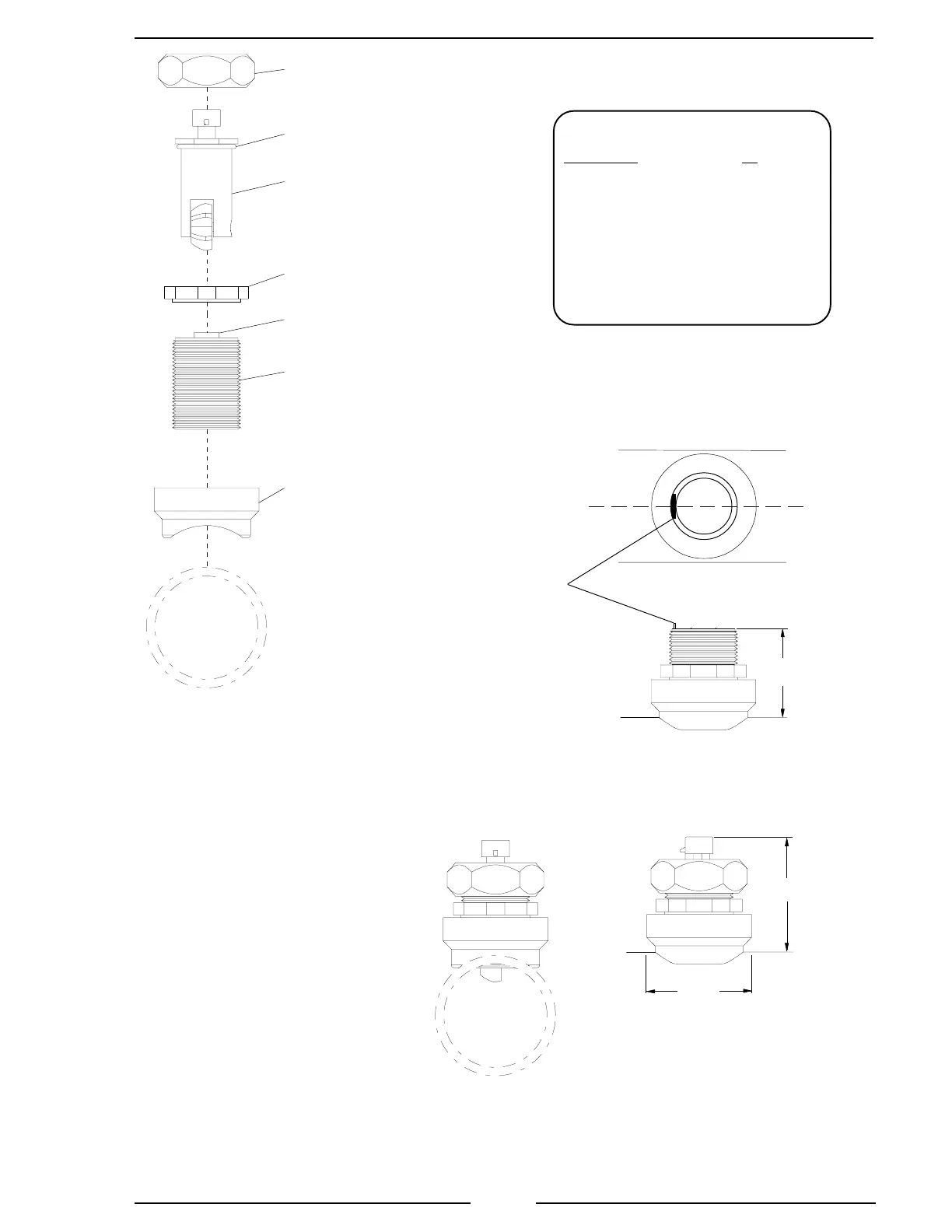
Figure 5. Weldment Installation
Note: Allow a minimum of 2 inches
clearence at the sensor top for removal/
installation of the connector.
Note: These dimensions are
typical and are given to be
used as an aid in determining
mounting locations for flow
sensors.
Retainer Cap
Paddlewheel
Flow Sensor
Tru-Seal
Locknut
Sensor
Housing
Weldment
Alignment
Tab
O-Ring
Make sure that the alignment tab is
centered on the pipe centerline.
2.8"
2.5"
Note: When the retainer cap is
tightened make sure the sensor
rim flat spot does not disengage
from the alignment tab and
allow the flow sensor to rotate.
Pipe Size Dimension
(Sch 40) A
1.5 1.95 to 1.80
2 1.95 to 1.80
2.5 1.90 to 1.75
3 1.88 to 1.73
3.5 1.88 to 1.73
4 1.85 to 1.70
Measurements are in inches.
Alignment
Tab
A
Pipe
Centerline

 Loading...
