FP4000 Rev0204
7
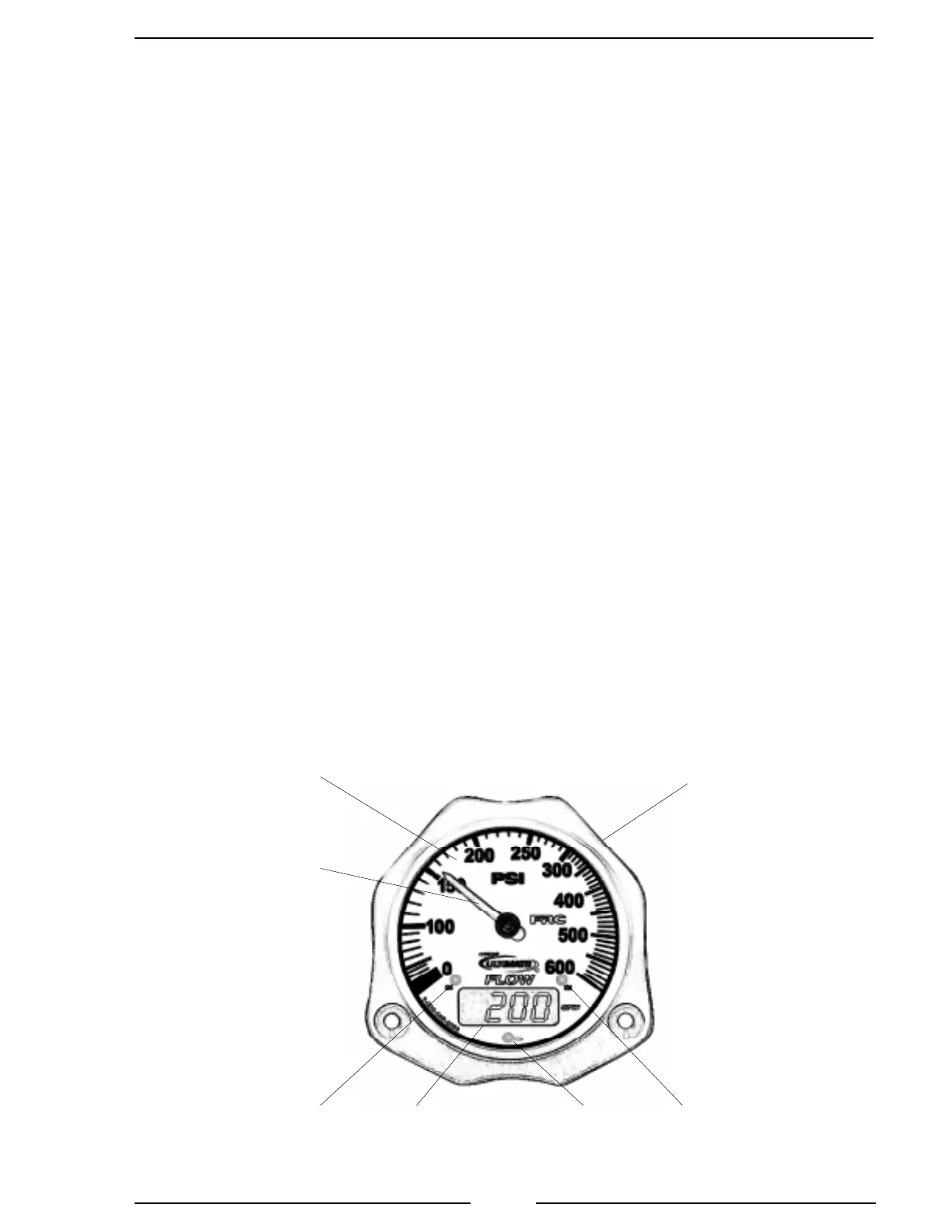
Controls and Indicators
All controls and indicators are located on the front of the display module. It contains
the pressure scale and indicating needle, a digital display, and the three magnet sensors.
(Refer to Figure 1.)
Pressure Display
The pressure scale is non-linear and is expanded between 100 and 250 PSI. This
provides for better visibility and more accurate readings in the normal operating range.
Digital Display
During normal operation this 4-digit LED display will indicate flow rate. When
the display module identification or program access modes are selected the digital
display shows module specific information, program codes, settings, and error codes.
See the Programming section for more information.
Magnet Sensors
The operator selected modes are accessed and inputs are made by using the three
magnet sensors M1, M2, and M3 located on the front of the display module. The M1
and M2 sensors are used to input data when in the program access mode. The M3
sensor is used to enter and exit these modes. See Programming section for more
information.
Magnet
The north pole of a small magnet is placed on the glass in close proximity to the
magnet sensor and then moved about 1 inch away to activate the sensor.
Figure 1. Controls and Indicators
M1 M2M3Digital
Display
Pressure
Scale
Pressure
Indicating
Needle
Optional Color
Coded Bezel

 Loading...
