FP4000 Rev0204
33
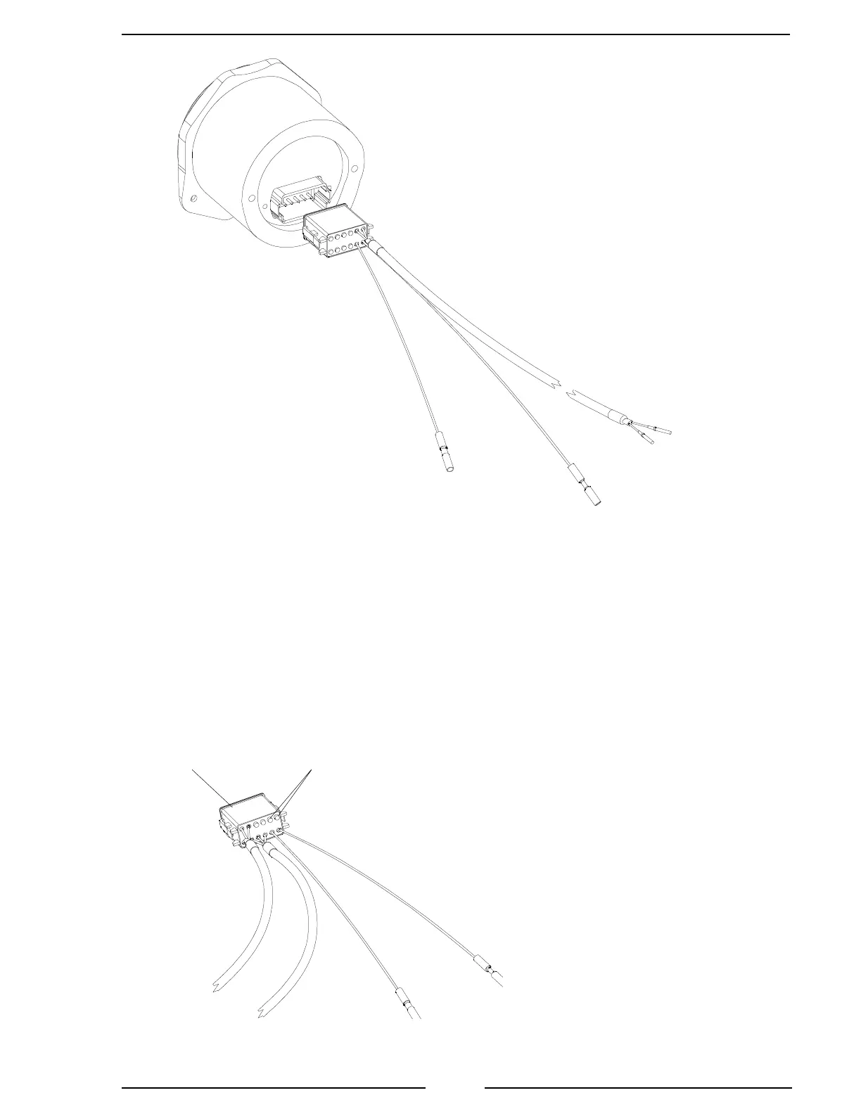
To Primary Display
Connector
Black Wire to Pin 11
Red Wire to Pin 12
Red Wire
9 - 30 VDC
Remote
Display
Figure 10. Remote Display Wiring
Pin Lock Pin Plugs
Note: The remote display connector
pinouts are the same as the primary
display connector pinouts.
Note: The pin lock and two pin plugs have to
be removed to insert the pins from the remote
display harness. Reinstall the pin lock after the
two pins from the remote are inserted.
Note: Minimum
wire size for power
is 18 AWG.
Note: To connect multiple displays on
the datalink:
Connect pin 11 of each display together.
Connect pin 12 of each display together.
Black Wire
Ground
Primary Display
Connector

 Loading...
