© Safe Fleet | September 2018 | All rights reserved
Document #: XE-SNB1-Install-PM-R0A
p. 10
inView 360 Fusion Installation Guide
Installing Power & Interface Components
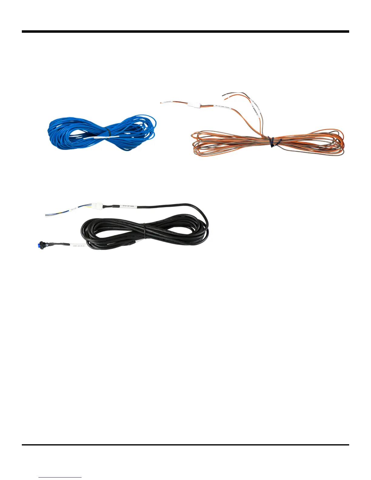
• Connect the GEAR (Blue) wire to the vehicle’s reverse signal source (via extension wire)� This source must be
positive (12v when the vehicle is put in reverse)�
• Connect the FLASHER connector (via extension cable) to the vehicle’s front turn signal sources (Orange for left,
Brown for right)� These sources must also be positive (12V when the left or right turn signals are on)�
Connecting the Driver Button
The Driver Button lets the operator switch between the front, rear, left, and right camera views on the in-cab monitor�
To install the driver button:
1� Choose a location in the vehicle� Ideally, the location should be within arm’s reach of the driver�
2� Drill a 7/16” hole�
3� Thread the button through the hole�
4� Tighten the nut to the underside of the button�
5� Connect the button to the extension cable�
6� Run the extension cable to the ECU�
7� Connect the extension cable to the BUTTON connector on the Power & Interface harness�
 Loading...