© Safe Fleet | September 2018 | All rights reserved
Document #: XE-SNB1-Install-PM-R0A
p. 6
inView 360 Fusion Installation Guide
Installation Diagram
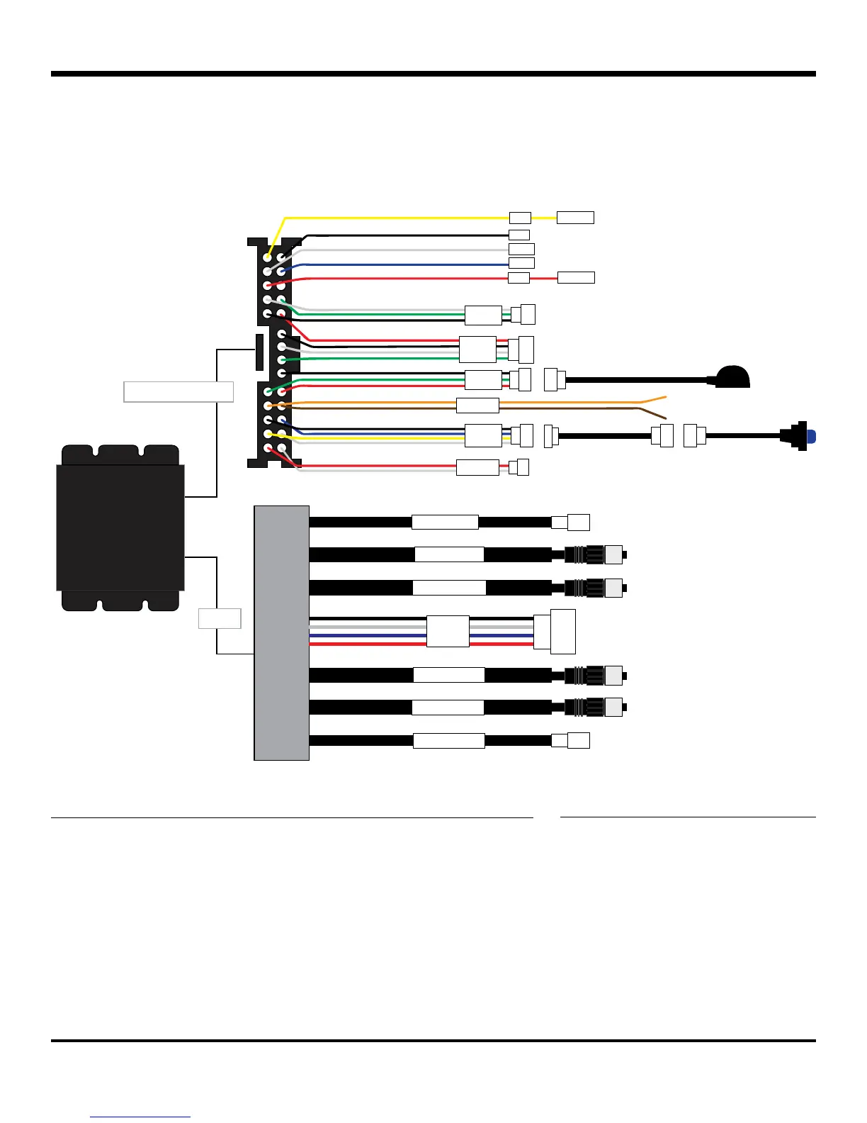
Installation Diagram
The inView 360-Fusion comes with two main connection harnesses, one for Power & Interface, and one for Video�
The following diagram provides a breakdown of each.
POWER & INTERFACEVIDEO
MCU UPDATECPU UPDATE
Power & Interface
Video
VBAT
GND
ACC
+3A Fuse
+1A Fuse
TOUCH
FLASHER
SPEAKER
OBD
IrDA
BUTTON
VOUT
GEAR
CVBS2
CVBS1
REAR CAM
DVR
FRONT CAM
RIGHT CAM
LEFT CAM
• VBAT - Yellow - Battery
• GND - Black - Ground
• VOUT - White - Not Used
• GEAR - Blue - Reverse
Signal
• ACC - Red - Ignition
• TOUCH - Not Used
• OBD - Not Used
• IrDA - Remote Control Sensor
• Flasher - Orange (Left), Brown
(Right) Signal
• BUTTON - Driver Button
• SPEAKER - Not Used
• CVBS1 - Monitor
• CVBS2 - DVR
• DVR - Not Used
Power & Interface Harness Legend Video Harness Legend
 Loading...