Home
Fresenius Medical Care
Medical Equipment
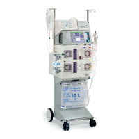
4008 E
Fresenius Medical Care 4008 E User Manual
4
of 1
of 1 rating
595 pages
Give review
Manual
Specs
To Next Page
To Next Page
To Previous Page
To Previous Page
Loading...
Fresenius Medical Care
4008
4/09.03
(TM)
8-261
8.31
P
.C.B. LP
923 T
raffic light (4008 H/S)
8.31.1
Description
P.C.B. LP
923 indicates the machine status:
–
green status indicator (operation)
–
yellow status indicator (warning/info)
–
red status indicator (alarm)
557
559
Table of Contents
Table of Contents
6
Section Page
7
1 Description of Machine Functions and Malfunctions
8
Description of the T1 Test
10
T1 Test Flow Diagram, Serial Program Steps
10
T1 Test Flow Diagram, Parallel Program Steps
12
Description of the T1 Test Incl. Error Messages
14
Description of Machine Errors During the Cleaning Programs
60
Error Messages after Turning Power on
77
Error Messages During Dialysis
78
Functional Description of the Modules
85
Blood Pump (Arterial)
85
Blood Pump (Single Needle), Optional
86
Heparin Pump
87
Air Detector
89
Functional Description of the Hydraulic Unit
90
Description of the Hydraulic Unit
92
Theory of Operation of the Balancing Chamber
94
Central Delivery System Option
98
Program Runs During the Cleaning Programs
99
Technical Safety Checks / Technical Measurement Checks / Maintenance
106
For 4008 Hemodialysis Systems and Options
108
Description - Technical Safety Checks and Maintenance
110
Checklist - Technical Safety Checks and Maintenance
120
Notes - Checking the Electrical Safety
124
Technical Measurement Checks and Maintenance Ki
128
For Options of 4008 Hemodialysis Systems
128
Technical Safety Checks and Maintenance for 4008 Hemodialysis Systems and Options
108
Technical Measurement Checks and Maintenance for Options of 4008 Hemodialysis Systems
128
Description - Technical Measurement Checks and Maintenance
130
Checklist - Technical Measurement Checks and Maintenance
132
TSC Checklist
134
Adjustment Instructions/Overview of the Dip Switches in the 4008
136
3 Adjustment Instructions
136
Overview of the DIP Switches in the 4008
136
Plus (Option)
141
Overview of the DIP Switches in the 4008
146
LP 631 (CPU 1) DIP Switch Array
146
LP 631 (CPU 1) DIP Switch Array
147
LP 632 (CPU 2) DIP Switch Array
148
LP 632 (CPU 2) DIP Switch Array
149
Calibration Mode
150
Basic Conditions
150
Messages on the Displays on the UF Monitor (4008 E/B) or on the Screen (4008 H/S)
150
Hydraulics
152
Reduced Water Inlet Pressure
152
Degassing Pump Pressure
154
Balancing Chamber Loading Pressure
156
Flow Pump Pressure
158
UF Pump Volume
160
CDS Pressure Switch
162
Air Detector
164
4 Calibration Program
166
Diagnostics Program
200
Default Chapter
202
General Notes
202
Menu Structure
204
Reading the Analog Inputs of CPU I
206
Reading the Analog Inputs of CPU
208
Reading the Digital Inputs of CPU I
209
Reading the Digital Inputs of CPU
214
Writing the Analog Outputs of CPU I
218
Writing the Analog Outputs of CPU
219
Writing the Digital Outputs of CPU I
220
Writing the Digital Outputs of CPU
226
Writing/Reading the Digital Outputs of CPU I
229
6 Setup Menu
232
Overview
238
Main Menu 4008 E/B Rev. 5.2
240
Main Menu 4008 H/S Rev. 4.3
266
7 Miscellaneous
296
Section Page/Circuit Diagrams and Circuit Descriptions
298
Section Page
298
8 Circuit Diagrams and Circuit Descriptions
298
Block Diagram 4008
302
AC Diagram 4008 E/H
304
AC Diagram 4008 B/S
306
Block Diagram of Voltage Supply
308
Block Diagram of Screen 4008 H/S
310
Connection Layout Diagram
312
Connection Diagram CAN Communication
313
Hydraulics Processor Block Diagram
314
LP 450-2 Level Detector Control (LD)
316
Description
316
LP 450-2 Level Detector Control (LD)
320
P.C.B. LP 493 Blood Leak Detector
328
Description
328
Circuit Diagram and Component Layout Diagram
329
LP 624 Control Board
332
LP 624 Control Board (BP)
332
Description
332
Circuit Diagram and Component Layout Diagram
335
P.C.B. LP 630 Motherboard
342
Lp 631 Cpu 1
350
Description
350
Lp 631 Cpu
350
Circuit Diagram and Component Layout Diagram
359
Lp 632 Cpu
362
Description
362
Circuit Diagram and Component Layout Diagram
367
LP 633 Input Board
382
Description
382
P.C.B. LP 634 Output Board
402
Description
402
P.C.B. LP 635 Display Board
426
Description
426
LP 636 External Connectors
444
P.C.B. LP 638 Power Supply
448
P.C.B. LP 639 Power Logic
456
LP 950 Control Board (HEP)
468
LP 644-4 Display Board (HEP)
476
LP 645 Position Sensor Membrane Pump
480
LP 647 Power Logic a (4008 B/S)
484
LP 649-2 Display Board (4008 B/S)
492
LP 742 Interference Filter
510
LP 743 Power Control 2 (4008 B/S)
514
LP 744 Power Control 1 (4008 B/S)
520
P.C.B. LP 747 Distribution Board
524
LP 748 Display Board (BP)
530
LP 763 Multi Interface Board
534
LP 922 Display Board (4008 S)
542
LP 923 Traffic Light (4008 H/S)
558
LP 924 Display Board (4008 H)
562
P.C.B. LP 941 Hydraulics Processor
578
4
Based on 1 rating
Ask a question
Give review
Questions and Answers:
Need help?
Do you have a question about the Fresenius Medical Care 4008 E and is the answer not in the manual?
Ask a question
Fresenius Medical Care 4008 E Specifications
General
Brand
Fresenius Medical Care
Model
4008 E
Category
Medical Equipment
Language
English
Related product manuals
Fresenius Medical Care 4008 S
408 pages
Fresenius Medical Care 4008 B
595 pages
Fresenius Medical Care 4008 H
595 pages
Fresenius Medical Care 4008 HDF
104 pages
Fresenius Medical Care 460018
75 pages
GranuFlo 450385
61 pages
GranuFlo 450368-03
67 pages
Fresenius Medical Care 5008
328 pages
Fresenius Medical Care 2008T
768 pages
Fresenius Medical Care 2008K2
66 pages
multiFiltrate
282 pages
Liberty Select
272 pages

 Loading...