ATTENTION! ?
More information on successful commissioning.
Note the following information about connecting the data communication cable to the
inverter.
▶
Use network cables of type CAT5 or higher.
▶
Use a mutual twisted cable pair for corresponding data lines (D+/D-, M1+/M1-).
▶
If the data lines are close to the mains cabling, use wires or cables that are designed
for 300 to 600 V (never less than the operating voltage).
▶
Use double-insulated or sheathed data lines when they are close to bare conduct-
ors.
▶
Use shielded twisted pair cables to avoid faults.
▶
Two wires can be installed in each terminal; the wires are twisted first, inserted into
the terminal and tightened.
Note: A loose wire can disable an entire area of the network.
▶
The data communication connections of the Fronius Smart Meter TS are electrically
isolated from hazardous voltages.
Terminating res-
istors - Explana-
tion of symbols
Inverter in the system
e. g. Fronius Symo
Meter - Fronius Smart Meter TS
Terminating resistor R 120 Ohm is set with a wire jumper between M-
and T.
Modbus RTU slave
e. g. Fronius Ohmpilot, Fronius Solar Battery, etc.
Terminating resistor
R 120 Ohm
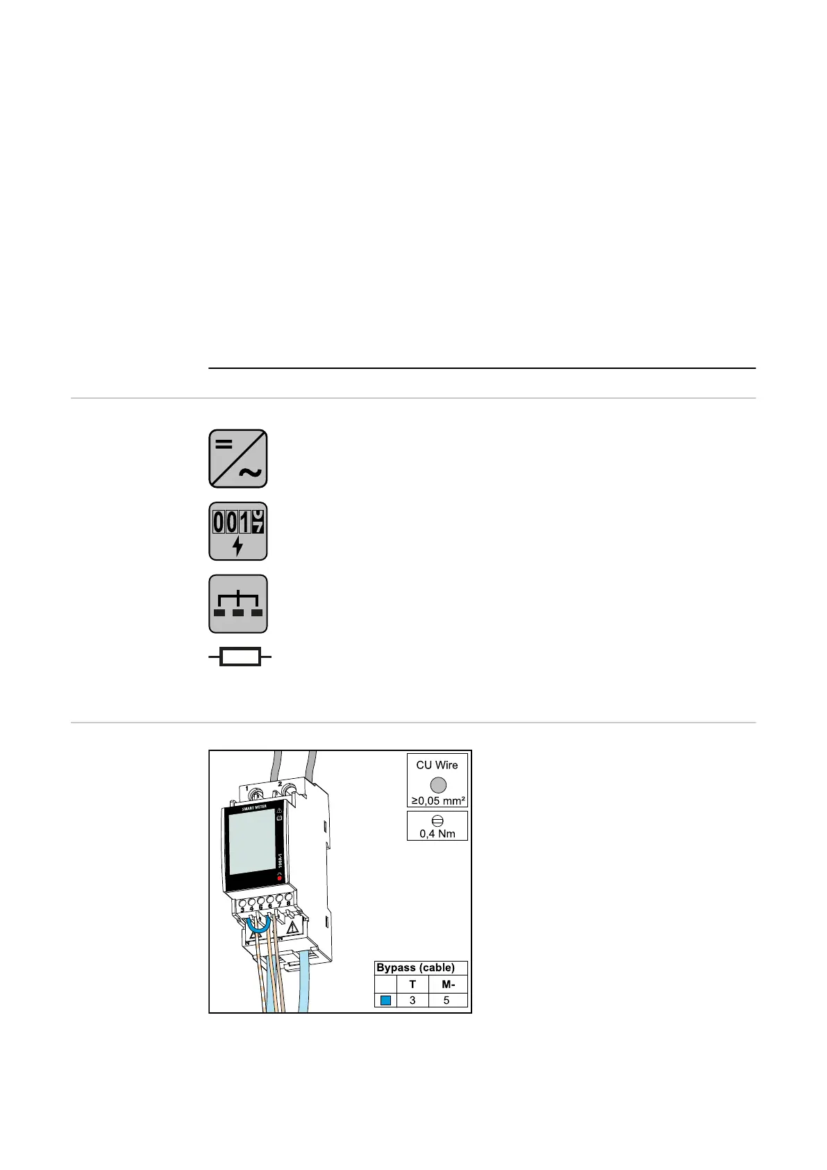
Connecting the
terminating res-
istor
The terminating resistor is integrated in the
Fronius Smart Meter TS and is manufac-
tured with a bridge between the M and T
connections (T = termination).
22

 Loading...