Do you have a question about the Fronius Smart Meter TS Series and is the answer not in the manual?
| Communication Interface | RS485, Modbus RTU, M-Bus, Ethernet (depending on model) |
|---|---|
| Protection Class | IP20 |
| Voltage Range | 3 x 230/400 V (depending on model) |
| Frequency | 50 Hz |
| Power Consumption | < 2 VA per phase |
| Mounting | DIN rail |
| Rated Voltage | 3 x 230/400 V (depending on model) |
Explains the meaning of safety symbols and warnings used in the manual.
Provides general safety guidelines and precautions for operating the device.
Details the operational or storage conditions for the device.
Specifies the qualifications required for personnel handling the device.
Outlines copyright information and user responsibility for data protection.
Defines the proper and intended application of the Fronius Smart Meter TS.
Locates technical data, markings, and safety symbols on the device itself.
Introduces the Fronius Smart Meter TS, its purpose, and basic functionality.
Lists the items included in the product package.
Illustrates the recommended installation locations for the meter in a system.
Provides a step-by-step guide for the installation process.
Covers mounting the device and requirements for protective circuits.
Explains the correct wiring procedures for mains voltage and data communication.
Guides on fitting protective covers and connecting data communication cables.
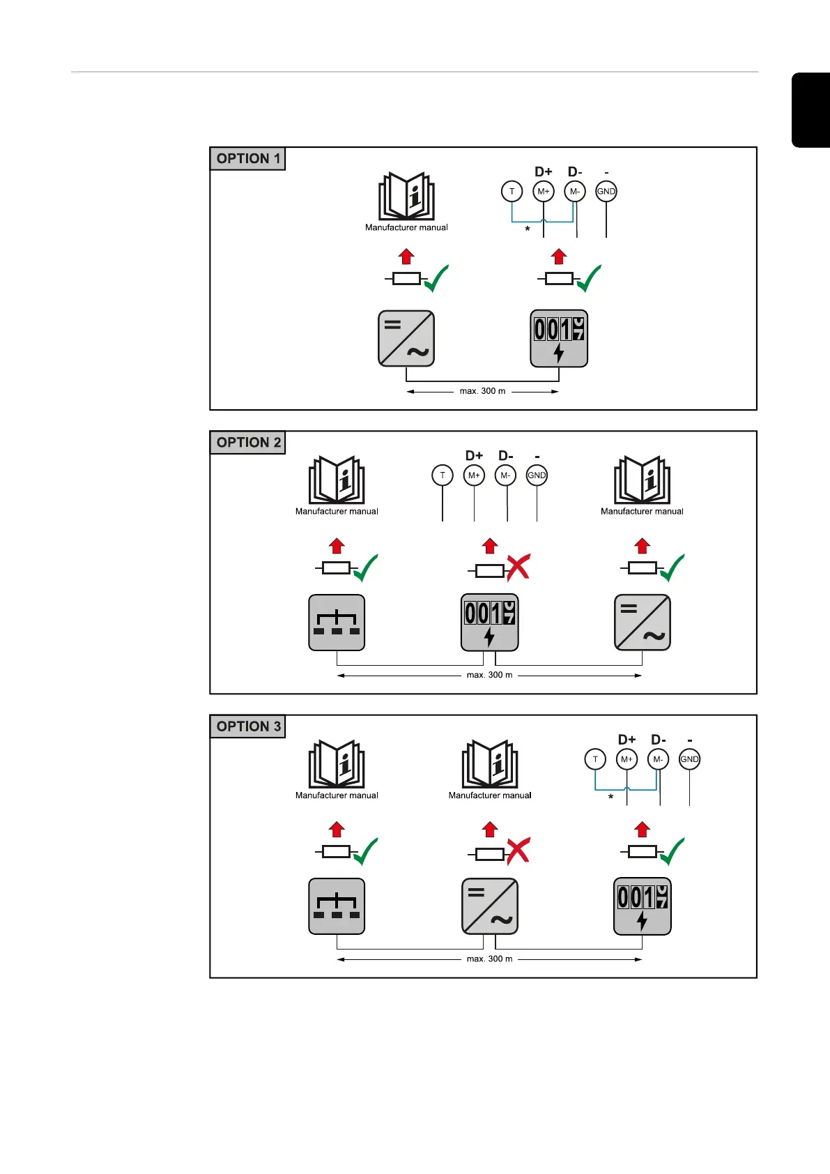
Explains the purpose and connection of terminating resistors for Modbus communication.
Details attaching the connection cover and explains multi-meter system symbols.
Details the device's menu hierarchy and available parameters for configuration.
Provides instructions on assigning unique Modbus addresses to meters in a multi-meter system.
Covers connecting and configuring the Smart Meter with SnapINverters.
Step-by-step guides for setting up the meter as primary or secondary.
Details the process of integrating the meter with GEN24 inverters.
Details measuring input, data output, RS485 communication, and insulation specifications.
Specifies operating range, temperature limits, housing, and terminal details.
Provides information on warranty terms and registration for the product.