8-3
8.4 Compliance with EMC Standards
8.4.1 General
The CE marking on inverters does not ensure that the entire equipment including our CE-marked products is
compliant with the EMC Directive. Therefore, CE marking for the equipment shall be the responsibility of the
equipment manufacturer. For this reason, Fuji Electric’s CE mark is indicated under the condition that the
product shall be used within equipment meeting all requirements for the relevant Directives. Instrumentation of
such equipment shall be the responsibility of the equipment manufacturer.
Generally, machinery or equipment includes not only our products but other devices as well. Manufacturers,
therefore, shall design the whole system to be compliant with the relevant Directives.
EMC certification testing is performed using the following wiring distances between the inverter and
motor (shielded wire):
・FRN0010LM2C-4□ to FRN0032LM2C-4□
:10m
8.4.2 Recommended installation procedure
To satisfy the requirements noted above, use inverters in combination with an external filter (option) dedicated to
Fuji inverters. In either case, mount inverters in accordance with the installation procedure given below. To
ensure the compliance, it is recommended that inverters be mounted in a metal panel. For details, refer to the
TS-LM2C-0001-v■-EMC filters for LM2C for EMC compliance. The document is a Technical Statement that will
describe the List of filters for LM2C for fulfilling the EMC compliance.
Note: ■ can be any number between 100 and 999 that means document revision.
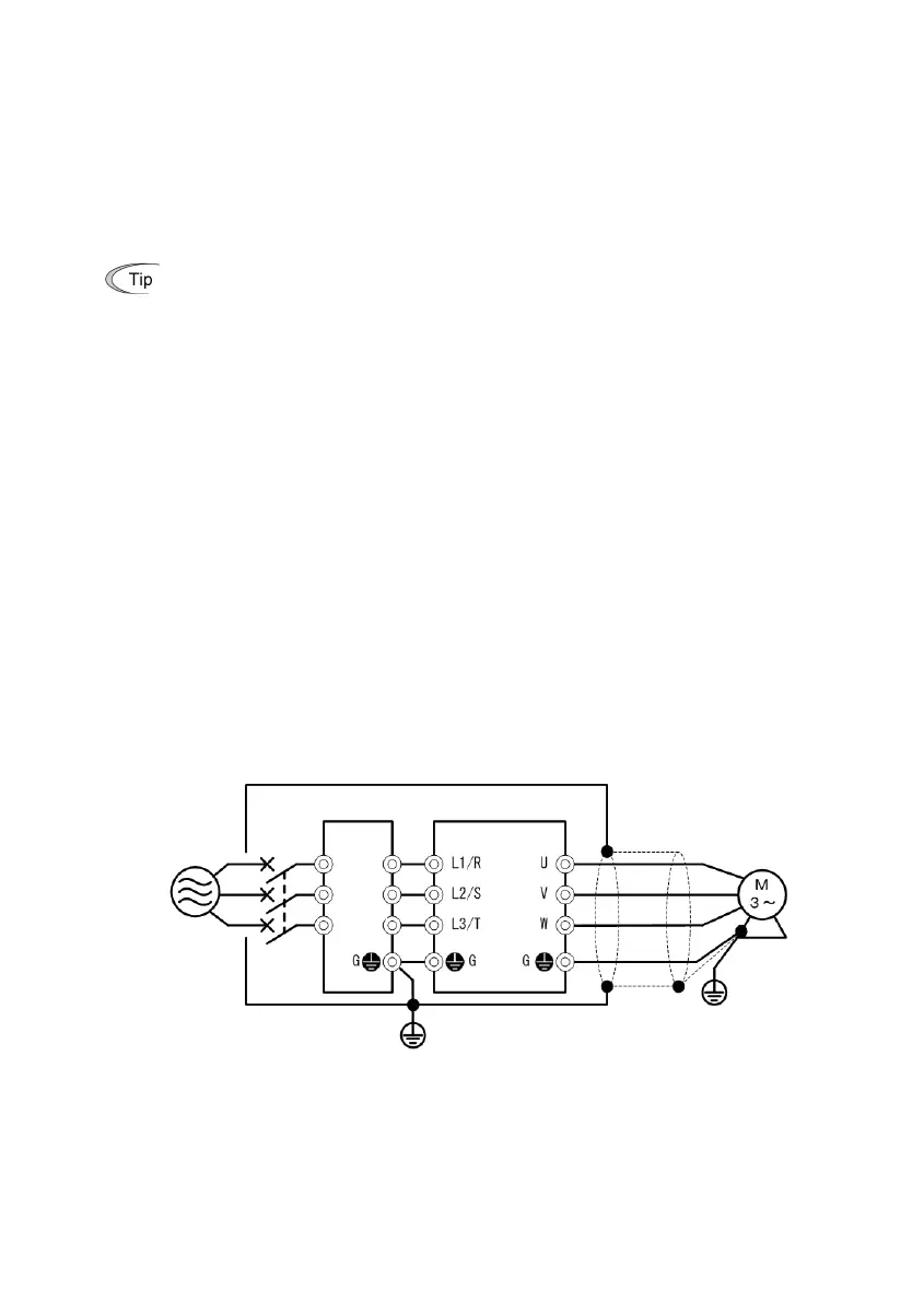
1) Mount the inverter and the filter on a grounded panel or metal plate. Use shielded wires for the motor cable
and route the cable as short as possible. Firmly clamp the shields to the metal plate to ground them.
Further, connect the shielding layers electrically to the grounding terminal of the motor.
2) For connection to inverter’s control terminals and for connection of the RS-485 communication or CAN-Bus
signal cable, use shielded wires. As with the motor connections, clamp the shields firmly to a grounded
panel.
3) If noise from the inverter exceeds the permissible level, enclose the inverter and its peripherals within a
metal panel as shown in Figure 8.1.
Figure 8.1 Installation inside a Panel
FRENIC-Lift
-
compliant
filter
(optional)
Note: Connect the shielding layer of
shielded cable to the motor and
panel electrically and ground the
motor and panel.
: With overcurrent protection

 Loading...


