5-1
Chapter 5 FUNCTION CODES
5.1 Function Code Tables
Function codes enable the FRENIC-Mini series of inverters to be set up to match your system
requirements.
Each function code consists of a 3-letter string. The first letter is an alphabet that identifies its group
and the following two letters are numerals that identify each individual code in the group. The
function codes are classified into seven groups:
Fundamental Functions (F codes), Extension
Terminal Functions (E codes), Control Functions of Frequency (C codes), Motor Parameters (P
codes), High Performance Functions (H codes), Application Functions (J codes), and Link Function
(y codes). To determine the property of each function code, set data to the function code.
The following descriptions supplement those given in the function code tables on page 5-3 and
subsequent pages.
Changing, validating, and saving function code data when the motor is running
Function codes are indicated by the following based on whether they can be changed or not when
the inverter is running:
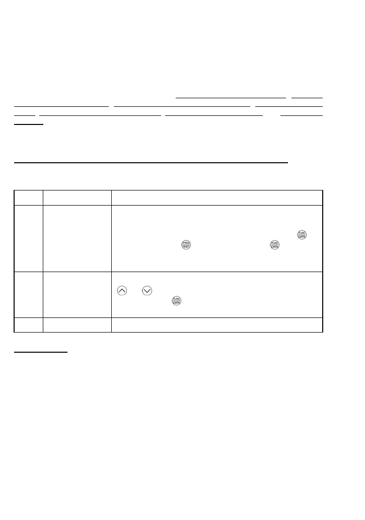
Notation Change when running Validating and saving function code data
Y* Possible
If the data of the codes marked with Y* is changed, the change
will immediately take effect; however, the change is not saved
into the inverter's memory. To save the change, press the
key. If you press the
key without pressing the key to exit
the current state, then the changed data will be discarded and
the previous data will take effect for the inverter operation.
Y Possible
The data of the codes marked with Y can be changed with the
and keys regardless of whether the motor is running or
not. Pressing the
key will make the change effective and
save it into the inverter's memory.
N Impossible —
Copying data
Connecting a remote keypad (option) to an inverter via the RS485 communications card (option)
allows copying the data stored in the inverter's memory into the keypad's memory (refer to Menu #7
"Data copying" in Programming mode). With this feature, you can easily transfer the data saved in a
source inverter to other destination inverters.
If the specifications of the source and destination inverters differ, some code data may not be copied
to ensure safe operation of your power system. Therefore, you need to set up the uncopied code
data individually as necessary. Whether data will be copied or not is detailed with the following
symbols in the "Data copy" column of the function code tables given below.
Y: Will be copied unconditionally.
Y1: Will not be copied if the rated capacity differs from the source inverter.
Y2: Will not be copied if the rated input voltage differs from the source inverter.
N: Will not be copied. (The function code marked "N" is not subject to the Verify operation, either.)
It is recommended that you set up those function codes which are not subject to the Copy operation
idually using Menu #1 "Data setting" as necessary. indiv
Refer to the Remote Keypad Instruction Manual (INR-SI47-0843-E) for details.
 Loading...