5-13
5.2 Overview of Function Codes
This section provides an overview of the function codes frequently used for the FRENIC-Mini series
of inverter.
For details about the function codes given below and other function codes not given below,
refer to the FRENIC-Mini User’s Manual (MEH446), Chapter 9 "FUNCTION CODES" and the
RS485 Communications User's Manual (MEH448).
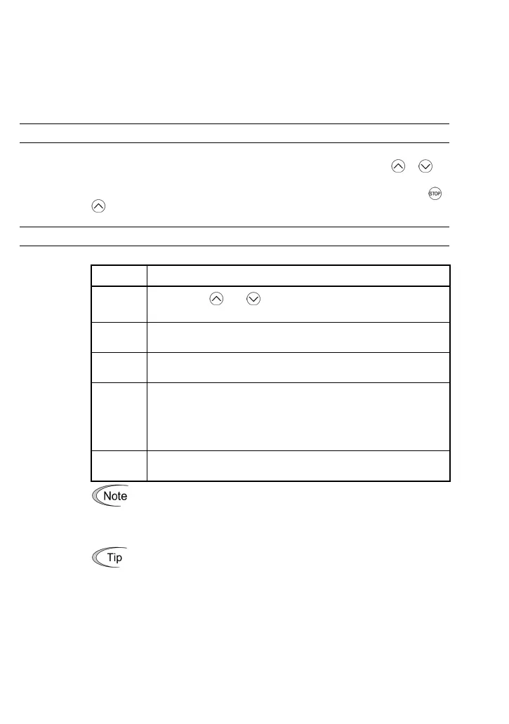
F00 Data Protection
Specifies whether function code data is to be protected from being accidentally
changed by keypad operation. If data protection is enabled (F00 = 1),
or key
operation to change data is disabled so that no function code data, except F00 data,
can be changed from the keypad. To change F00 data, simultaneous keying of
+
keys is required.
F01, C30 Frequency Command 1 and 2
Selects the devices to set the set frequency for driving the motor.
Set F01 to: To do this
0 Enable the and keys on the built-in keypad. (Refer to
Chapter 3 "OPERATION USING THE KEYPAD.")
1 Enable the voltage input to terminal [12] (0 to +10 VDC, maximum
frequency obtained at +10 VDC).
2 Enable the current input to terminal [C1] (+4 to +20 mA DC,
maximum frequency obtained at +20 mA DC).
3 Enable the sum of voltage and current inputs to terminals [12] and
[C1]. See the two items listed above for the setting range and
maximum frequencies.
Note: If the sum exceeds the maximum frequency, the maximum
frequency will apply.
4 Enable the built-in potentiometer (POT). (Maximum frequency
obtained at full scale of the POT)
• There are other frequency command means (such as the
communications facility, multistep frequency, etc.) with higher priorit
than that of F01. Refer to the FRENIC-Mini User's Manual (MEH446),
Chapter 4, Section 4.2 "Drive Frequency Command Generator" fo
more details.
• For frequency commands by terminals [12] (voltage) and [C1]
(current) and by the built-in potentiometer, setting the gain and bias
changes the relationship between those frequency commands and the
drive frequency to enable matching your system requirements. Refe
to function code F18 for details.
• For the inputs to terminals [12] (voltage) and [C1] (current), low-pass
filters can be enabled. Refer to the FRENIC-Mini User's Manual
(MEH446), Chapter 9, "FUNCTION CODES" for details.
In addition to "F01 Frequency set 1," "C30: Frequency set 2" is available. To switch
between them, use the terminal command (Hz2/Hz1). For details of the (Hz2/Hz1),
refer to "E01 to E03, E98, and E99: Command Assignment to Terminals [X1] to [X3],
[FWD], and [REV]."
 Loading...