En-9
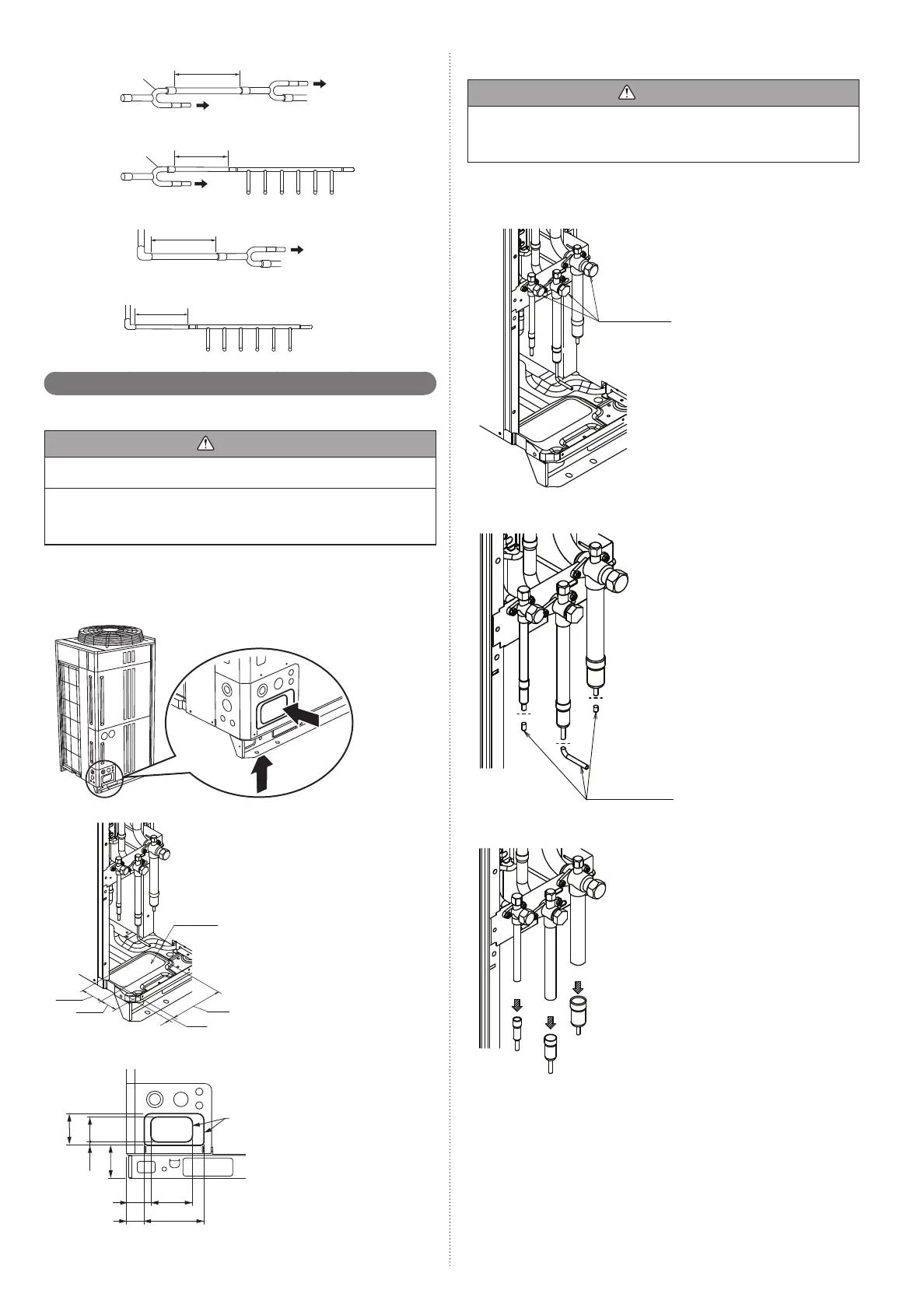
Main pipe
0.5 m or more
To indoo r u n it
To indoo r u n it
To indoo r u n it
Main pipe
0.5 m or more
To indoo r
unit
Separation tube
or
Header
0.5 m or more
0.5 m or more
To indoo r u n it
or
Header
Separation tube
To indoo r
unit
Piping method5. 3.
Opening the knockout hole5. 3. 1.
CAUTION
Be careful to prevent panel deformation or damaged while opening the knockout
hole.
To prevent cutting of the wiring after the knockout hole was opened, remove the
burrs along the edge.
In addition, to prevent rusting, painting the edge with rust preventive paint is recom-
mended.
The piping can be connected from 2 directions; the front or the bottom.
(Knockout holes are provided so that the piping can be connected from 2 different
directions.)
Use the front knockout hole, as required.
A Knockout positionFig.
B Detail of knockout position (bottom)Fig.
Knockout hole
(Unit: mm)
197
42
82
80
C Detail of knockout position (front)Fig.
75
95
10
100
43
73
199
125
Knockout
hole
(Unit: mm)
Removing the pinch pipe5. 3. 2.
WARNING
Remove the pinch pipe only when the internal gas is completely drained as shown
on the below instructions.
If gas still remains inside, the piping may crack if you melt the brazing fi ller metal of
the junction area with a burner.
Before connecting the piping, remove the pinch pipe in accordance with the following
instructions:
Verify that the liquid side , suction gas side and discharge gas side 3-way valves 1)
are closed.
3-way valves
Cut the end of the liquid side , suction gas side and discharge gas side pinch pipe 2)
and vent the gas inside the pinch pipe.
End of pinch pipe
After all the gas is vented, melt the brazing fi ller metal on connecting part using a 3)
torch and remove the pinch pipe.
9378945111_IM.indb Sec1:99378945111_IM.indb Sec1:9 2012/11/14 09:48:592012/11/14 09:48:59

 Loading...


