En-13
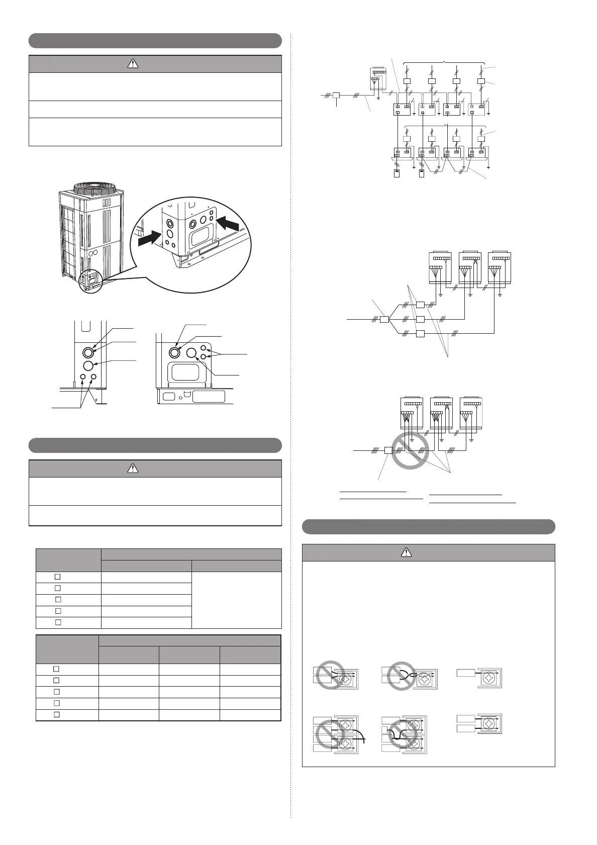
In case of connected outdoor unitFig.
GOOD
Breaker
Transmission cable
Remote controller cable
Breaker
400 V 3ø 50 Hz
230 V 1ø 50 Hz
Outdoor unit
power supply cable
RB unit
power supply
cable
Indoor unit
power supply
cable
230 v 1ø 50 Hz
Selecting main breaker and main power supply cable when connecting multiple (2)
outdoor units
Main breaker: Main breaker ≥ Total Sub breaker
(Refer to the table in item (1) for the
sub breaker capacity)
In case of connected 3 outdoor unitFig.
GOOD
Sub
breaker
Outdoor unit power supply cable
400 V 3ø
50 Hz
Main
breaker
Example of bad breaker wiring(3)
PROHIBITED
400 V 3ø
50 Hz
Outdoor unit
Power supply cable
PROHIBITED: crossover
power supply wiring prohibited
Breaker
PROHIBITED: install a
breaker for each outdoor unit
Transmission line6. 5.
CAUTION
Caution when wiring cable•
When stripping off the coating of lead wire, always use the exclusive tool such as
a wire stripper. If there is no exclusive tool available necessarily, carefully strip the
coating by a cutter etc. so that the conductive wire is not damaged.
If it is damaged, it may lead to an open circuit and a communication error.
Pay attention to the following points while attaching wires on the terminal board.•
Do not attach 2 wires on one side.
Do not twist wires.
Do not cross the wires.
Do not shorted at edge at root.
PROHIBITED
GOOD
PROHIBITED
PROHIBITED PROHIBITED
GOOD
2pcs at one side
Shorted at edge
Wires twisted
Shorted at root
1 wire
2 wires
Knockout hole6. 3.
CAUTION
Seal the wiring route hole with putty (fi eld supply) such that there are no gaps.
Small insects or animals that are trapped in the outdoor unit may cause a short circuit
in the electrical component box.
Be careful not to deform or scratch the panel while opening the knockout holes.
After opening the knockout hole, remove the burr on the edges to prevent snapping
of cables.
It is recommended to apply rust proof paint on the edges to prevent rust.
Electric wires can be connected from the front or from the left.
(Knockout holes are prepared so that wiring can be made from 2 different directions.)
Use the knockout holes on the front and the left separately when necessary.
< Left view >
< Front view >
(Unit: mm)
Ø 50
Ø 34.5
Ø 43.7
Ø 22.2
Ø 50
Ø 34.5
Ø 43.7
Ø 22.2
Selecting power supply cable and breaker6. 4.
CAUTION
Obtain the distribution network operator's agreement about the power capacity of
the power supply system, specifi cation of the cable and the harmonic current, and
etc. when you connect the outdoor unit with the power supply.
Regulation of wire size and circuit breaker differs from each locality, please refer in
accordance with local rules.
Refer to the table for the wiring and breaker specifi cations of each installation condition
.
Selecting power supply cable and breaker when connecting 1 outdoor unit(1)
MODEL
Breaker (Time delay fuse or circuit capacity)
Fuse capacity (A) Leakage current
AJ
A72GALH 20
100mA
0.1sec or less
AJ
A90GALH 25
AJ
108GALH
25
AJ
126GALH 40
AJ
144GALH 40
MODEL
Outdoor unit power supply cable
Power supply
cable (mm
2
)
Ground wire (mm
2
)
Critical wiring
length (m)
AJ
A72GALH 4 4 51
AJ
A90GALH 6 6 62
AJ
108GALH 6 6 62
AJ
126GALH 10 10 64
AJ
144GALH 10 10 64
These values are recommended data. 1)
Specifi cation: Use conformed cord with Type 60245 IEC66 2)
Max. wire length: Set a length so that the voltage drop is less than 2%. Increase 3)
the wire diameter when the wire length is long.
9378945111_IM.indb Sec1:139378945111_IM.indb Sec1:13 2012/11/14 09:49:032012/11/14 09:49:03

 Loading...


