En-6
Lifting by forklift
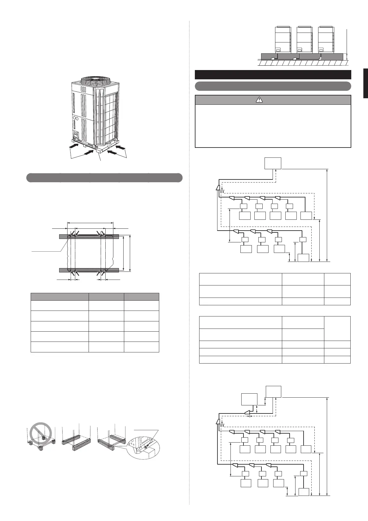
When using the forklift to lift the unit, pass the forklift arms through the opening •
space as shown in below.
Front : Bottom of the wooden delivery pallet.
Side : Space between pallet and cabinet.
(Enable to remove the pallet from cabinet.)
Be careful not to damaged.•
Lifting by forklift (Manual forklift: hand-fork)
When using the manual forklift to lift the unit, pass the forklift arms through to the •
opening space between pallet and cabinet from side.
Fork (Forklift)
Delivery pallet
Fork (forklift) or
Fork (Manual forklift)
<Front>
<Side>
Installation the unit3. 5.
Install the unit level. (within 3 degrees).•
Install 4 or more anchor bolts at the 8 locations indicated by arrows (Fig. A).•
Place the left and right anchor bolts at a distance further away than the dimensions •
of A in the Table A.
(Excluding the case where anchor bolts are installed at 8 places.)
AFig.
732
765
80
80
160160
B
A
Hole: 12 × 17
(8 places)
Bottom view
(Unit: mm)
Table.A
Model name A B
AJ
□
A72GALH 610 930
AJ
□
A90GALH 610 930
AJ
□
108GALH 610 930
AJ
□
126GALH 920 1240
AJ
□
144GALH 920 1240
To minimize vibration, do not install the outdoor unit directly on the ground.•
Instead, install it on top of a fi rm platform (such as concrete block). (Fig. B)
The foundation base should be able to support the product and the foot width of •
the product should be more than 46.5mm.
Depending on the installation condition, vibration during the operation of the unit •
may cause noise and vibration.
Install vibration-proofi ng materials (such as rubber pads).
Consider the removal space of the connection piping when installing the founda-•
tion.
Secure the equipment fi rmly with anchor bolts, washers, and nuts.•
BFig.
Bolt (M10)
*Do not use a four-corner support foundation.
GOODPROHIBITED GOOD
CFig.
200 mm
or more
When installing piping from the
bottom of the outdoor units, the
required space under the outdoor
unit ≥ 200mm.
* Install the branch kit horizontally.
SYSTEM CONFIGURATION4.
System confi guration4. 1.
CAUTION
When connecting multiple outdoor units, set the nearest outdoor unit to the indoor •
unit on the refrigerant pipe as the master unit.
When connecting multiple outdoor units, install the outdoor unit with the largest •
nominal system capacity nearest to the indoor unit on the refrigerant pipe, fol-
lowed by those with less nominal system capacities.
[Capacity: Master ≥ Slave]
Always keep to the limit on the total amount of refrigerant. Exceeding the limit •
on the total amount of refrigerant when charging will lead to malfunction.
In case of 1 outdoor unit connected A)
A Fig.
O.U.
(Master)
O.U. :Outdoor unit
RB :RB unit
I.U. :Indoor unit
RB
RB RB RB RB
I.U. I.U. I.U. I.U. I.U.
I.U.
I.U.I.U.I.U.
RB RB RB
f
p
H3
H4
H5
H1
H2
*1
(*1: Cooling only)
a
Allowable pip length (actual pipe length)•
Between master outdoor unit and the
farthest indoor unit
165 m or less
a+f
a+p
Between the fi rst separation tube and the
farthest indoor unit
60 m or less f, p
Total pipe length 700 m or less Total
Allowable height difference•
Between outdoor unit and indoor unit (When
indoor unit is installed below)
50 m or less
H1
Between outdoor unit and indoor unit (When
outdoor unit is installed below)
40 m or less
Between indoor units 15 m or less H2, H3
Between RB unit and indoor unit 5 m or less H4
Between RB units 15 m or less H5
Total refrigerant amount : 35 kg or less•
In case of 2 outdoor units connected B)
B Fig.
O.U.-2
(Slave)
O.U.-1
(Master)
f
e
a
H4
p
H3
H5
H6
H1
H2
*1
(*1: Cooling only)
b
O.U. :Outdoor unit
RB :RB unit
I.U. :Indoor unit
RB RB RB RB
RB RB RB RB
I.U.
I.U.I.U.I.U.
I.U. I.U. I.U. I.U. I.U.
9378945111_IM.indb Sec1:69378945111_IM.indb Sec1:6 2012/11/14 09:48:572012/11/14 09:48:57

 Loading...


