En-17
1
2
+
+ -
*5
*6
*7
P. C .B
CN136
(Black)
or CN137
(Blue)
DC power supply
(External) 12 to 24 V
Connected load
(Operation Indicator or
Error Indicator)
connected unit
5: Provide a DC12 to 24 V power supply. *
Select a power supply capacity with an ample surplus for the connected load.
6: The allowable current is 30 mA or less. *
Provide a load resistance such that the current becomes 30 mA or less.
7: Polarity is [+] for pin 1 and [-] for pin 2. Connect correctly.*
Do not impress a voltage exceeding 24 V across pins 1-2.
A twisted pair cable (0.33 mm*
2
(AWG22)) should be used. Maximum length of
cable is 150 m.
Use an external input and output cable with appropriate external dimension, de-*
pending on the number of cables to be installed.
Base heater terminal6. 7. 4.
Service parts : WIRE WITH CONNECTOR (9708642000)
This is the output signal for base heater. Output signal ON, when the outdoor tem-
perature goes down below 2°C, and signal OFF at the outdoor temperature 4°C.
1
2
3
4
P. C .B
CN115
(Black)
*8
AC240 V
(For rated 415 V power supply)
Cable
(0.82 mm
2
(18AWG))
Base heater *9
8: Connect to pin 1 and pin 3. No connection pin 2 and pin 4.*
9: The allowable current is 1 A or less.*
FIELD SETTING7.
CAUTION
Discharge the static electricity from your body before setting up the DIP switches.
Never touch the terminals or the patterns on the parts that are mounted on the
board.
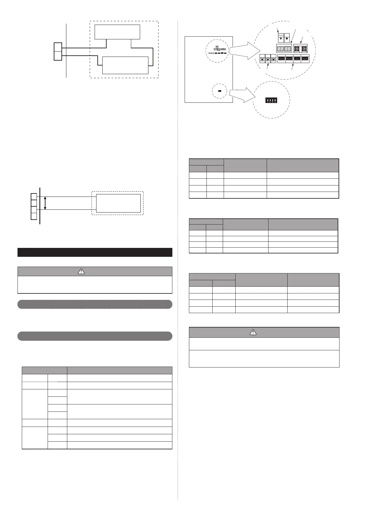
Field setting switches7. 1.
Remove the service panel of the outdoor unit and the cover of the electrical compo-
nent box to access the PC board of the outdoor unit.
PC board switches for various settings and LED indicators are shown in the fi gure.
DIP switch setting7. 2.
List of Settings7. 2. 1.
SET3 and SET5 must be set for the DIP switch.
Confi gure the settings before turning on the power. Settings for SET1, SET2, and
SET4 DIP switches are factory default ones. Do not change them.
DIP Switch Function
SET1 1-4 Forbidden
SET2 1-4 Forbidden
SET3
1
Outdoor unit address setting
2
3
Setting for number of slave units
4
SET4 1-4 Forbidden
SET5
1-2 Number of outdoor units installed
3 Forbidden
4 Terminal resistor setting
X 10 X 1
7 Segment
LED indicator
Push button
LED lamp
POWER
LED105
LED104
REF AD
SET 1
SW101
SET 2
SW102
SET 3
SW103
SET 4
SW104
ERROR
MODE
LED101
(GREEN)
MODE
/EXIT
SELECT
ENTER
SW106
SW107
SW108
SW109
SW105
LED102
(RED)
Rotary switch
Outdoor unit PC board
DIP switch
SET5
Settings to be confi gured locally7. 2. 2.
Outdoor unit address setting(1)
When 2 or 3 outdoor units are installed to 1 refrigerant system, set the address for
each outdoor unit.
Set the address for all outdoor units.
SET3
Outdoor unit address Remarks
12
OFF OFF 0 Master unit (Factory setting)
OFF ON 1 Slave unit 1
ON OFF 2 Slave unit 2
ON ON - Forbidden
Nu(2) mber of slave units setting for outdoor unit
Set the number of slave units connected to 1 refrigerant system.
Set only the master unit.
SET3
Number of connectable
outdoor units
Remarks
34
OFF OFF 0 Master unit only (Factory setting)
OFF ON 1 1 slave unit connected
ON OFF 2 2 slave unit connected
ON ON - Forbidden
Number o(3) f outdoor units installed
The number of outdoor units installed in 1 refrigerant system must be set.
Set for all outdoor units.
SET5
Number of outdoor units Remarks
12
OFF OFF 1 (Factory setting)
OFF ON 2 -
ON OFF 3 -
ON ON - Forbidden
Terminal resistor setting7. 2. 3.
Caution
Be sure to set the terminal resistor according to specifi cations.
Set the terminal resistor for every network segment (NS).
If terminal resistor is set in multiple devices, the overall communication system
may be damaged.
If terminal resistor is not set in a device, abnormal communication may occur.
Be sure to• set 1 terminal resistor in a network segment. You can set the terminal
resistor at the outdoor unit or signal amplifi er.
When settin• g the terminal resistor of a signal amplifi er, refer to the installation
manual of the signal amplifi er.
When settin• g multiple terminal resistors, take note of the following items.
How many network segments are there in a VRF system?
①
Where will you set the terminal resistors in a network segment? (Condition for 1
②
segment: Total number of outdoor and indoor units and signal amplifi ers is less
than 64, or the total length of the transmission cable is less than 500m)
How many outdoor units are connected to 1 refrigerant system?
③
9378945111_IM.indb Sec1:179378945111_IM.indb Sec1:17 2012/11/14 09:49:052012/11/14 09:49:05

 Loading...


