En-8
D (Between separation tube and RB unitTable.
)
Model code
Cooling capacity of
indoor unit (kW)
Outside diameter mm (in)
Liquid pipe
Discharge
Gas pipe
Suction
Gas pipe
07, 09, 12, 14 2.2, 2.8, 3.6, 4.0, 4.5 6.35 (1/4") 9.52 (3/8") 12.70 (1/2")
18, 24, 30 5.6, 7.1, 8.0, 9.0 9.52 (3/8") 12.70 (1/2") 15.88 (5/8")
36, 45, 54 11.2, 12.5, 14.0 9.52 (3/8") 12.70 (1/2") 19.05 (3/4")
60 18.0 9.52 (3/8") 15.88 (5/8") 19.05 (3/4")
72, 90 22.4, 25.0 12.70 (1/2") 19.05 (3/4") 22.22 (7/8")
Use a standard separation tube for pipe branching. Do not use a T tube as it does not
separate the refrigerant evenly.
E (Between separation tubes or RB unit and separation tube)Table.
Total cooling capacity
of indoor unit (kW)
Outside diameter mm (in) Separation tube
Liquid pipe Gas pipe for 2 pipes
4.4 to 11.1 9.52 (3/8") 15.88 (5/8")
UTP-AX090A or
UTR-BP090X
11.2 to 13.9 9.52 (3/8") 19.05 (3/4")
14.0 to 28.0 12.70 (1/2") 22.22 (7/8")
28.1 to 44.7 12.70 (1/2") 28.58 (1-1/8")
UTP-AX180A or
UTR-BP180X
44.8 to 56.0 15.88 (5/8") 28.58 (1-1/8")
56.1 to 80.0 15.88 (5/8") 34.92 (1-3/8")
UTP-AX567A or
UTR-BP567X
80.1 to 95.0 19.05 (3/4") 34.92 (1-3/8")
95.1 or more 19.05 (3/4") 41.27 (1-5/8")
* If the selected pipe diameter based on table "E" becomes larger than the pipe diameter
based on table "C", please select the pipe whose diameter is equal to the table "C".
Gas pipe of table "E" should be compared with suction gas pipe of table "C."
(If pipe diameter E > C, select pipe size from table C)
* "Total cooling capacity of indoor unit" is the total value for the cooling capacity of indoor
unit connected downstream.
F (Between separation tube and indoor unit or RB unit andTable.
indoor unit)
Model code
Cooling capacity of
indoor unit (kW)
Outside diameter mm (in)
Liquid pipe Gas pipe
07, 09, 12, 14 2.2, 2.8, 3.6, 4.0, 4.5 6.35 (1/4") 12.70 (1/2")
18, 24, 30 5.6, 7.1, 8.0, 9.0 9.52 (3/8") 15.88 (5/8")
36, 45, 54 11.2, 12.5, 14.0 9.52 (3/8") 19.05 (3/4")
60 18.0 9.52 (3/8") 19.05 (3/4")
72, 90 22.4, 25.0 12.70 (1/2") 22.22 (7/8")
G (Separation tube / Header)Table.
Separation tube•
Total cooling capacity
of indoor unit (kW)
Separation tube
*5
for 2 pipes for 3 pipes
28.0 or less UTP-AX090A or UTR-BP090X UTP-BX090A
28.1 to 56.0 UTP-AX180A or UTR-BP180X UTP-BX180A
56.1 or more UTP-AX567A or UTR-BP567X UTP-BX567A
Header•
Total cooling
capacity of indoor
unit (kW)
Header
*5
for 2 pipes for 3 pipes
3-6 Branches 3-8 Branches 3-6 Branches 3-8 Branches
28.0 or less UTR-H0906L UTR-H0908L UTP-J0906A UTP-J0908A
28.1 to 56.0 UTR-H1806L UTR-H1808L UTP-J1806A UTP-J1808A
For the installation method, refer to the section on "Indoor unit pipe connections" *5.
below.
Protection of pipes4. 3.
Protect the pipes to prevent the entry of moisture and dust.•
Especially pay attention when passing the pipes through a hole or connecting the •
end of a pipe to the outdoor unit.
Location Working period
Protection method
Outdoor
1 month or more Pinch pipes
Less than 1 month Pinch or tape pipes
Indoor
—
Pinch or tape pipes
PIPE INSTALLATION5.
Brazing5. 1.
CAUTION
If air or different type of refrigerant enters
the refrigeration cycle, the internal pres-
sure in the refrigeration cycle will become
abnormally high and prevent the unit from
exerting its full performance.
Fig.
Pressure regulating valve
Brazing area
Nitrogen gas
Cap
Apply nitrogen gas while brazing the
pipes.
Nitrogen gas pressure: 0.02 MPa (= suf-
fi cient pressure to be felt on the back of
your hand or more)
If a pipe is brazed without applying nitrogen gas, it will create an oxidation fi lm.
This can degrade performance or damage the parts in the unit (such as the com-
pressor or valves).
Do not use fl ux to braze pipes. If the fl ux is the chlorine type, it will cause the pipes
to corrode.
In addition, if the fl ux contains fl uoride, it will affect the refrigerant piping system due to
deterioration of refrigerant oil.
For brazing material, use phosphor copper that does not require fl ux.
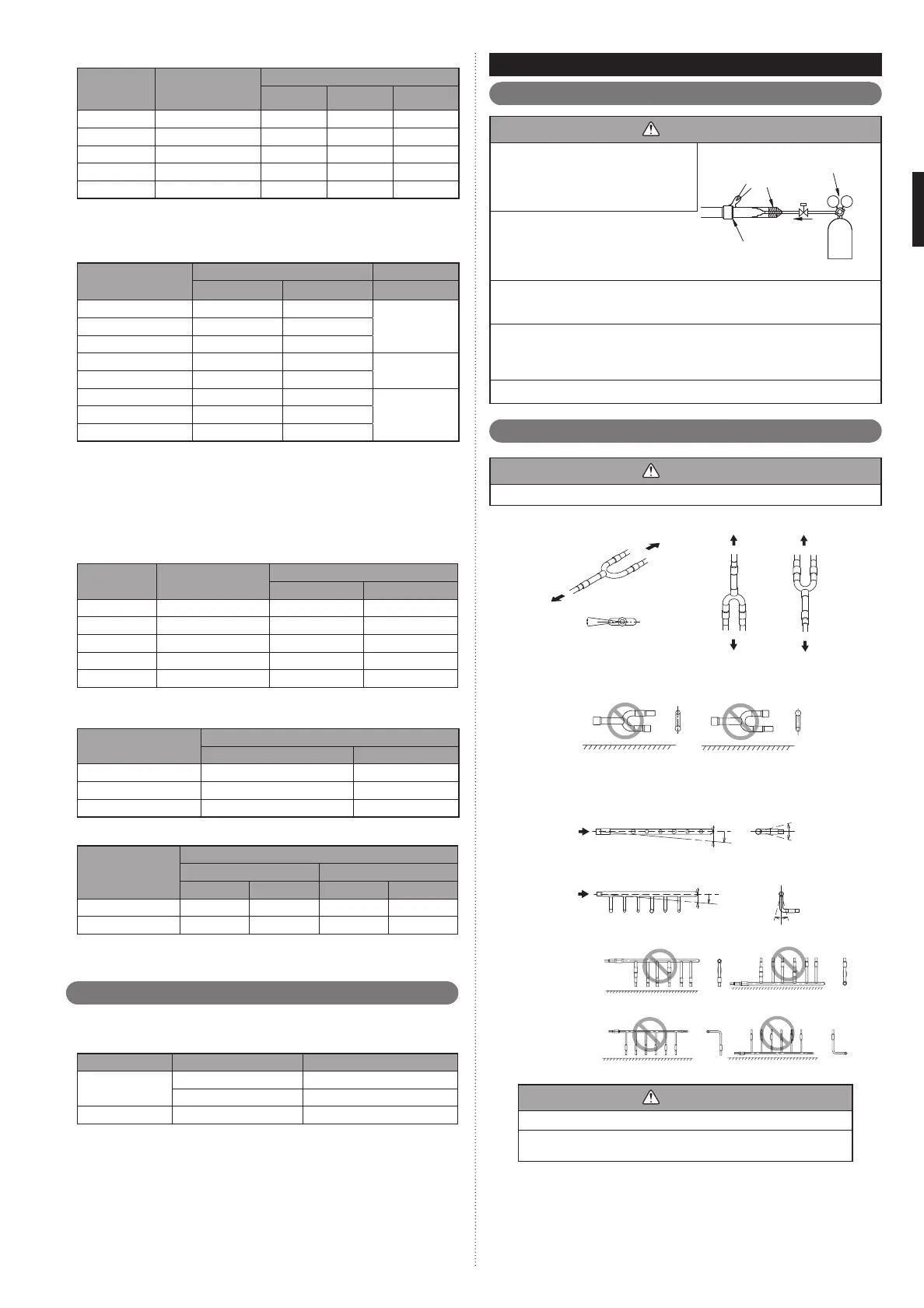
Indoor unit pipe connections5. 2.
CAUTION
For details, refer to the Installation Instruction Sheet of each part.
Separation tube
A
B
A
B
B
A
GOOD
Horizontal
Vertical
Horizontal line
or
± 15°
A : Outdoor unit or Refrigerant branch kit
B : Indoor unit or Refrigerant branch kit
PROHIBITED
Header
C
H
1
A
1
B
1
D
H
2
A2
B2
GOOD
Horizontal line
Horizontal
line
VIEW D
VIEW C
Horizontal
line
Vertical
line
Gas pipe
Liquid pipe
Outdoor
unit side
Outdoor
unit side
H
1
= 0 to 10 mm
H
2
= 0 to 10 mm
PROHIBITED PROHIBITED
(α
1
: 0° to 1°)
β
1
: -10° to 10°
(α
2
: 0° to 1°)
β
2
: -10° to 10°
CAUTION
Do not connect a separation tube after a header.
Leave the distance 0.5 m or more for straight part to branch tube and
header.
9378945111_IM.indb Sec1:89378945111_IM.indb Sec1:8 2012/11/14 09:48:582012/11/14 09:48:58

 Loading...


