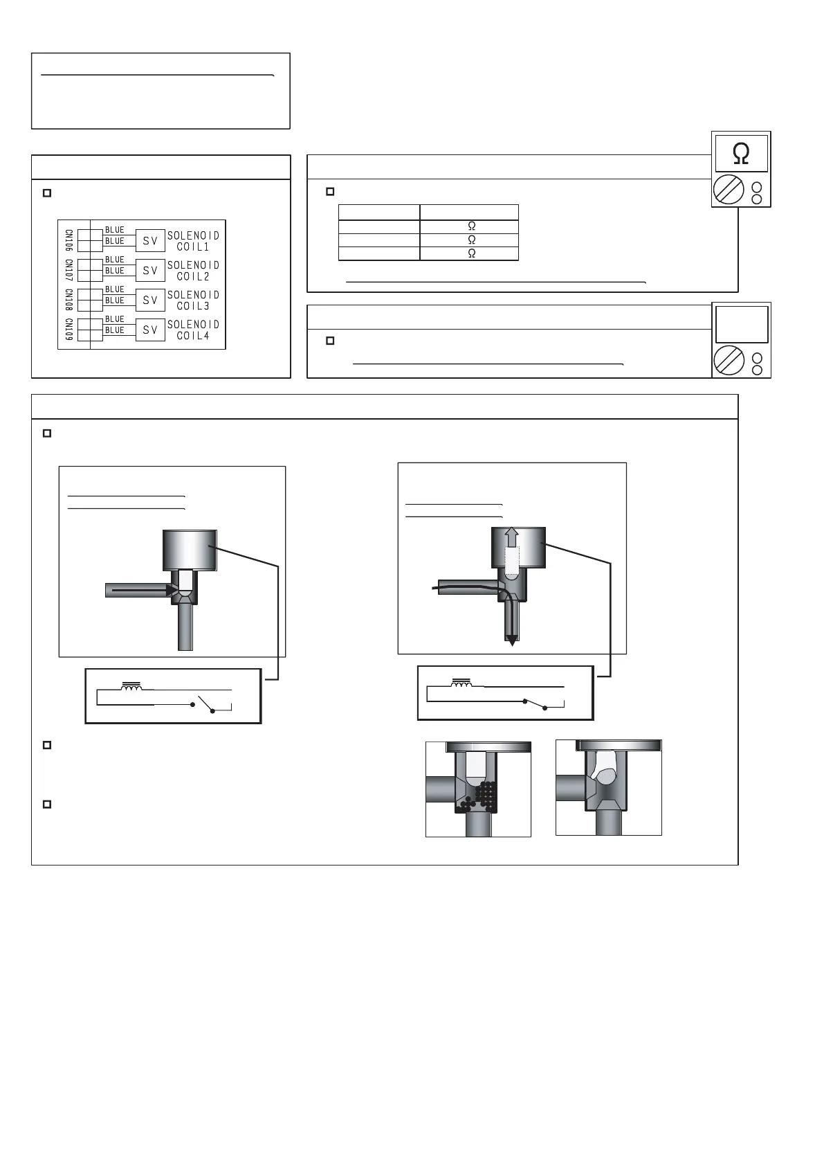
Check Point 1 : Check connections
Check connection of connector.
(Loose connector or open cable)
Check Point 3 : Check Voltage from Main PCB
Remove connector and check the voltage (AC208- 230V).
>> If the voltage does not appear, replace Main PCB.
Check Point 2 : Check Solenoid Coil
Remove connector and check if coil is open.
>> If Resistance value is abnormal, replace Solenoid Coil.
SERVICE PARTS INFORMATION 18
Outdoor Unit Solenoid Valve
(SV1, SV2, SV3, SV4)
Pipe (In)
Pipe (Out)
Pipe (In)
Pipe (Out)
AC
AC
SOLENOIDE COIL
SOLENOIDE COIL
Normal Operation
Pipe (In) TEMP. Normal,
Pipe (Out) TEMP.Normal
Protection Function (Refer to 2-6-1),
Special Operation
(Defrost, Oil recovery, Start-up)
Pipe (In) TEMP. Hi,
Pipe (Out) TEMP. Hi
Normal TEMP.
Normal TEMP.
Hi TEMP.
Hi TEMP.
OPEN
CLOSE
Check Point 4-1 : Check opening & closing operation of SV1, SV2
Depending on either during operation or protection control, check if Valve is operating normally.
(When Valve opens, Inlet and Outlet temperature is raised.)
(1)
(2)
If the valve closes by removing the connector of the valve
which does not close, it is considered to be Main PCB
failure. Replace Main PCB.
If it does not close by removing connector, there is a
possibility of (1) clogging by dirt, or (2) deformation by
the heat at the time of Solenoid Valve installation.
In this case, replace Solenoid Valve.
AC
13
12
13
12
13
12
13
12
Solenoid Coil Resistance value
SV1 1324 +7%
SV2, SV3 1495 +7%
SV4 1434.5 +10%
-
-
-
04-111
Resistance value 68 F(20
°
C)
°
 Loading...