03-13
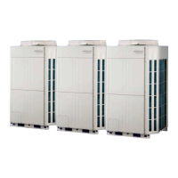
3-7-3 PCBs layout
Single type
Multi type
-Upper side-
- Upper side -
SV connector
SV connector
DIP SW
SET 1
DIP SW
SET 2
DIP SW
SET 1
Transmission PCB2
Transmission PCB1
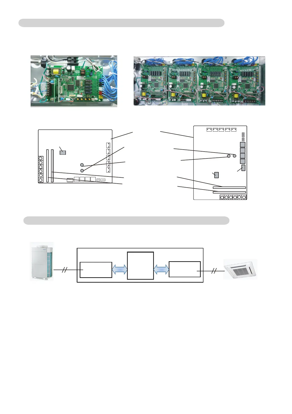
Transmission
PCB2
Transmission
PCB1
Main PCB
RB Unit
OU.
IU.
Transmission PCB1: Pulse signal communication between IU. and RB Main
Transmission PCB2: Pulse signal communication between OU. and RB Main
Main PCB: Pulse signal communication between Transmission PCB1 and Transmission PCB2
*The transmission PCB1 and The transmission PCB2 are the same part.
- Caution -
When the Main PCB is newly installed to the RB unit, the address setting is required.
The RBG Address number has to be set as the same address of connecting indoor unit.
(When a connection port of RB unit has a multi indoor unit connection, the younget address number of
indoor unit has to be given to the main PCB of RB.)
Error indication LED
(Red)
Power supply indication
LED (Green)
3-7-4 PCB component
Main PCB
 Loading...