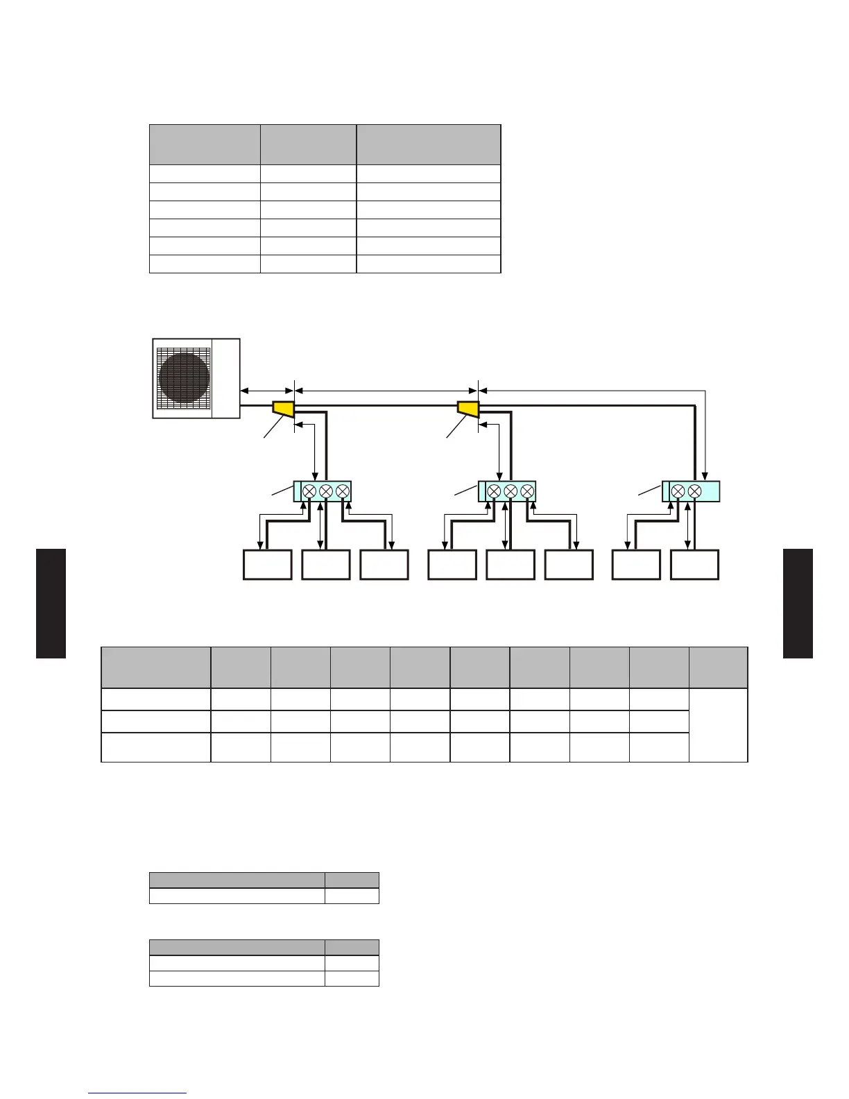
6. SYSTEM DESIGN
EXAMPLE OF PIPING DESIGN2-6.
Rated capacity of cooling
Model code
Capacity class
(kW)
Rated capacity of
cooling (kW)
07 2.0 2.05
09 2.5 2.64
12 3.5 3.52
14 4.0 4.10
18 5.0 5.27
24 7. 0 7.03
EXAMPLE 1
21 3 54 6 87
a b
d
f g hi j kl m
e
c
Outdoor unit
Separation
tube
Branch box Branch box Branch box
Separation
tube
Indoor unit Indoor unitIndoor unit Indoor unit Indoor unitIndoor unit Indoor unit Indoor unit
(2.0kW) (2.0kW)(2.0kW) (2.0kW) (2.0kW)(2.0kW) (2.0kW) (2.0kW)
System conguration
(Indoor units)
1 2 3 4 5 6 7 8
Total
capacity
(kW)
Model name AS07 AS07 AS07 AS07 AS07 AS07 AS07 AS07
16.4
Capacity class (kW) 2.0 2.0 2.0 2.0 2.0 2.0 2.0 2.0
Rated capacity of
cooling (kW)
2.05 2.05 2.05 2.05 2.05 2.05 2.05 2.05
Capacity ratio
(Total capacity of indoor units) / (Capacity of outdoor unit)
= (16.4) / (14.0) = 117.1% (Within 80% to 130%)
Selection of separation tube
Model Q'ty
UTP-SX248A 2
Selection of branch box
Model Q'ty
UTP-PY03A (3 branches) 2
UTP-PY02A (2 branches) 1
- (06 - 19) -
SYSTEM
DESIGN
SYSTEM
DESIGN
 Loading...