6. SYSTEM DESIGN
INDOOR UNIT7-2.
Indoor unit type
EXTERNAL INPUT
EXTERNAL OUTPUT
Control input
Operation status
output
Fresh air control
output
Auxiliary heater
output
Error status output
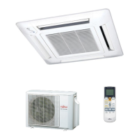
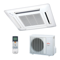
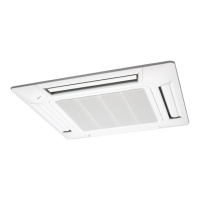
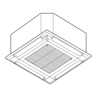
Compact
Cassette
- -
Slim Duct
-
Wall Mounted
- -
(LU / LM types)
Floor / Ceiling
- - -
Floor
- - -
EXTERNAL INPUT7-2-1.
CONTROL INPUT (Operation/Stop or Forced stop)
Compact
Cassette
Slim Duct
Wall Mounted
Floor / Ceiling Floor
LJ LU / LM LF
Connector CN102 CN102 CN303 CNA01 CN14 CN102 CN14
The air conditioner can be remotely operated by means of the following on-site work.
"Operation/Stop" mode or "Forced stop" mode can be selected with function setting of indoor unit.
Unit operation is started at the following contents by adding the contact input of a commercial ON/OFF switch to a
connector on the external control PC board and turning it ON.
Unit operation Initial setting after power is ON
Starting mode other than initial setting
Operation mode Auto changeover Mode at previous operation
Set temperature 24°C Temperature at previous operation
ir ow ode AUTO Mode at previous operation
Air direction (swing) Standard air direction (swing OFF) Air direction at previous operation
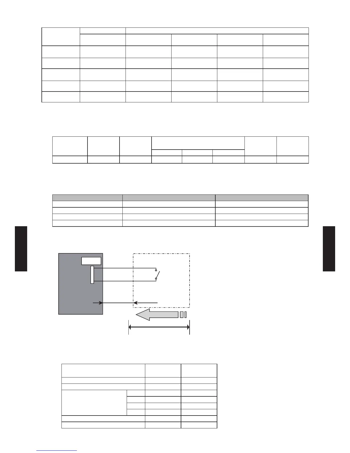
Circuit diagram example
*1 PC board of Communication kit is used for Wall mounted type (LJ, LU, LM).
*2 Make the distance from the PC board to the connected unit within 10 m.
Contact capacity: DC 24 V or more, 10 mA or more.
Indoor unit type
1 Pin
(Polarity)
3 Pin
(Polarity)
Compact Cassette - +
Slim Duct - +
Wall Mounted
LJ + -
LU - +
LM - +
LF - +
Floor / Ceiling - +
Floor - +
Indoor unit
control PC board *1
Connector
1
3
Signal
Field supply
10 m *2
Connected unit
Ex.) Switch
- (06 - 113) -
SYSTEM
DESIGN
SYSTEM
DESIGN
 Loading...