6. SYSTEM DESIGN
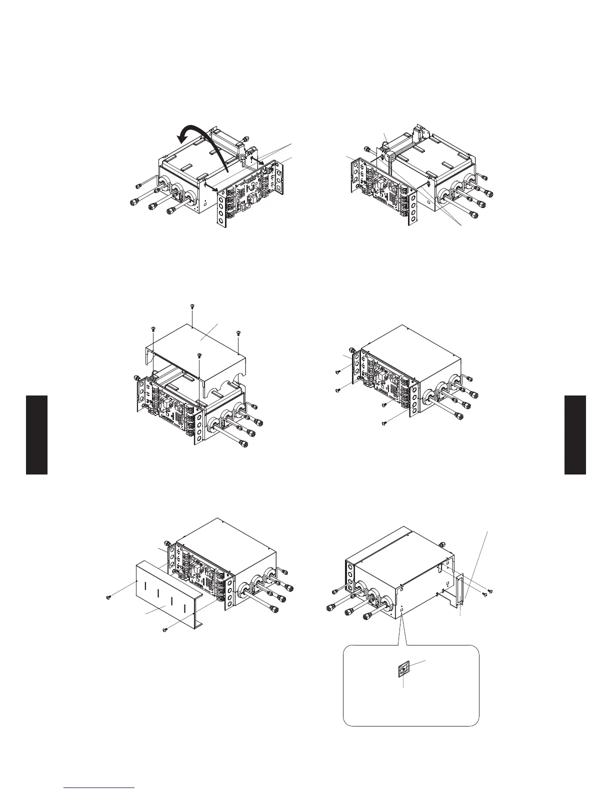
To the opposite side
Control box
Remove the control
box by lifting up and
out through slots
nsert and the contro
box using the slots
The lead wire
runs here
eoe the contro bo as shown in the gure
and then change the positioning to the opposite
side.
(6) Attach the control box to the main unit as
shown in the gure.
Control box
Bottom panel
(7) Attach the bottom panel and secure it with the
screws (4 pieces).
(8) Secure the control box with the screws
(4 pieces).
Control box
Control box cover
Seal
(Accessory)
the sea so each hoe
(4 places) is covered
Wiring cover
Secure the wiring
cover by inserting into
the slots
(9) Attach the control box cover and secure it with
the screws (2 places).
(10) Attach the wiring cover and secure it with the
screws (2 places).
the seas on the ain unit paces.
- (06 - 33) -
SYSTEM
DESIGN
SYSTEM
DESIGN
 Loading...