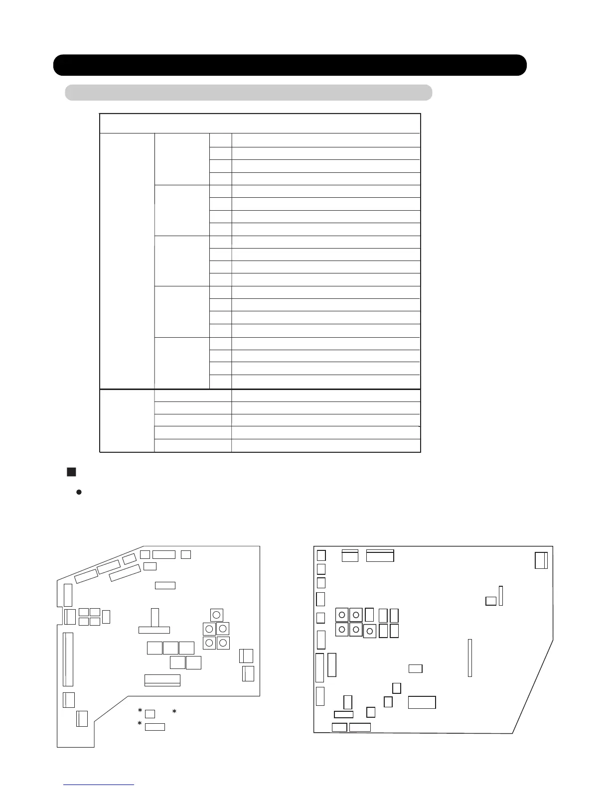
2-1 PCB LAYOUTS
2-1-1 INDOOR UNIT CONTROL CIRCUIT BOARD
2. FUNCTION OF PRINTED CIRCUIT BOARD
02-01
Indoor unit
SW 1
SW 2
DIP SW
SW 3
SW 4
Room temp correct coefficient of heating 1
Room temp correct coefficient of heating 2
Room temp correct coefficient of cooling
Forbidden(Indoor unit fan speed switch 1)
Forbidden(Indoor unit fan speed switch 2)
Forbidden(Indoor unit fan speed switch 3)
Extermal input select edge / pulse
Forbidden(Indoor unit model code)
1
2
3
4
1
2
3
4
1
2
3
4
1
2
3
4
Filter check validity / invalidity
Forbidden(Indoor unit model code)
Forbidden(Indoor unit model code)
Forbidden(Indoor unit model code)
SW 6
SW 7
SW 8
SW 9
SW 10
Indoor unit address switch
Forbidden
Rotary SW
Forbidden
Forbidden
Forbidden
Auto restart validity / invalidity
Refrigeration circuit address 1
Refrigeration circuit address 2
Remote controller address
Indoor unit control circuit board
SWITCH POSITION
Wireless remote controller custom code switch 1
1
2
3
4
Wireless remote controller custom code switch 2
Frost prevention temperature shift switch
Draft prevention setting switch
SW 5
CN27
CN18
CN19 CN20 CN21
CN22 CN23
CN24
CN25
CN26
CN11
CN12
CN13
CN14
CN1
CN2
CN4
CN5
CN10
CN6
CN3
CN17
CN16
CN15
SW1
SW2
SW3 SW4
SW5
SW7
SW9
SW6
SW8
SW10
CN201
CN101
CN23
CN1
CN9
CN16
CN7
CN4
CN13
CN11
CN6
CN5
CN19
CN12
CN8
CN22
CN24
CN21
CN20
CN17
CN18
CN14
CN3
CN25
CN15
CN26
SW1
SW2
SW3
SW4
SW5
SW7
SW9
SW6
SW8
SW10
For AB / AU / AR types indoor unit
For AS / AW types indoor unit
CN101 and CN201 exist
in the PCB of power supply.
 Loading...