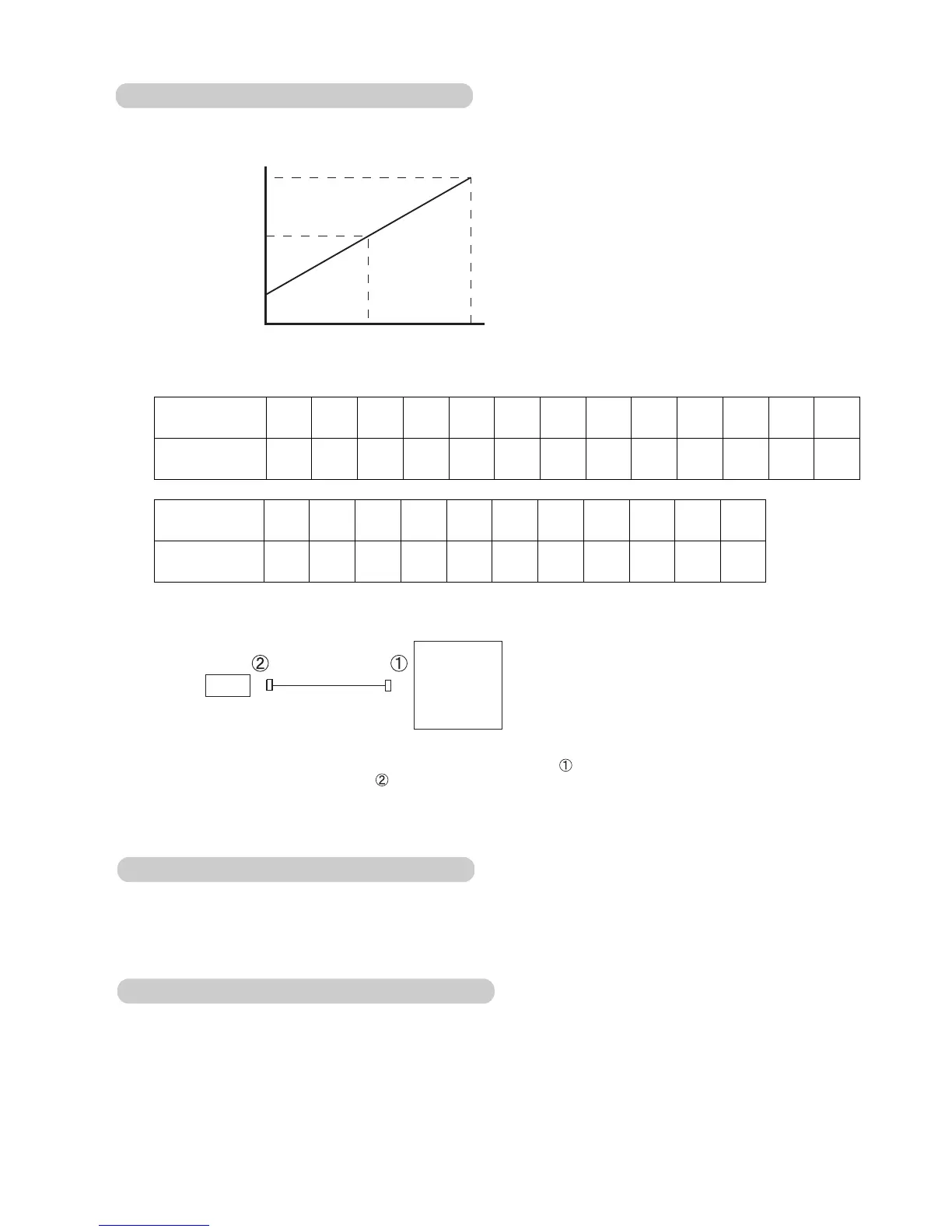
When installing the pressure sensor, connect a lead wire to the PCB ( ), thereafter connect the other end
of a lead wire to the pressure sensor ( ). When disconnecting, do the opposite procedure.
Be careful not to install other than above procedure, otherwise the pressure sensor can be failed.
0 1.75 3.5
1
3
5
Pressure
Output
MPa
V
1) Characteristics of pressure sensor
2) Check point of replacing pressure sensor
7-2-2 PRESSURE SENSOR
Pressure sensor
Printed circuit board
Lead wire
Pressure
(MPa)
Output
0.00
0.00
0.10
1.11
0.20
1.21
0.30
1.33
0.40
1.45
0.50
1.56
0.60
1.68
0.70
1.80
0.80
1.91
0.90
2.01
1.00
2.13
1.20
2.36
1.40
2.60
1.60
2.81
1.80
3.05
2.00
3.28
2.20
3.50
2.40
3.73
2.60
3.96
2.80
4.20
3.00
4.41
3.20
4.65
3.40
4.88
3.50
4.98
OUTPUT VOLTAGE OF THE PRESSURE SENSORS ( HP,LP )
(V)
Pressure
(MPa)
Output
(V)
07-04
7-2-3 ELECTRIC EXPANSION VALVE
When the electric expansion valve is locked cause by failure, it emits click noise. Confirming the noise
emission is done by touching any implement like a screw driver.
7-2-4 RB UNIT
When the RB unit is failed, it can be concerned one of the valve such as discharge valve, suction valve
and bypass is locked. The relation between open/close status of
each valve of RB unit and operating mode
is shown in 4-3-1.
 Loading...