2. WIRING
2-5
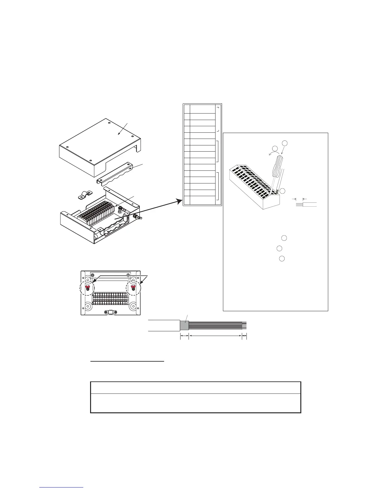
2.2 Junction Box IC-318
Use the junction box IC-318 to connect the distress alert/received call unit IC-305 and
other units (max. four units) to the communication unit. Unfasten four screws to re-
move the units cover to connect cables.
For connection, use the optional 5 pair cable CO-SPEVV-SB-C 0.2x5P, JIS cable (Ja-
pan Industrial Standard) TTYCS-4(LA) or equivalent.
Input/output sentences
The following sentences can be input/output with the navigator connected.
Input sentences
BWC, BWR, DBT, DTM, GGA, GLL, GNS, GSA, MTW, RMA, RMB, RMC,
VDO, VDR, VTG, WPL, ZDA
Cover
Terminal board
Procedure
1. Insert from direction 1 .
2. Tilt slightly toward 2 .
3. Insert cable core to 3 .
Core 7 mm
1
2
3
Vcc
GND
TD/RD-A
TD/RD-B
NC
ALM-H
RD-A(NAV)
RD-B(NAV)
GND
SSAS OUT-H
SSAS OUT-C
SSAS IN-H
SSAS IN-C
SSAS CTR
IC-305/306
1
2
3
4
5
6
7
8
9
10
11
12
13
14
15
Cable clamp
4. Pull out the screwdriver.
Note 1: Do not insert the wire deeply, to
prevent pinching its sheath.
Note 2: Pull the wire slightly to confirm
that it is in the slot correctly.
Sticker for
connection of
other equipment
ALM-C
For TTYCSLA cable, use the screws
and crimp-on lugs shown below to
connect the drain wire of that cable.
Screws and crimp-on lugs
(supplied in the IC-318)
IC-318, inside view
Fold back
15 mm
90 mm
7 mm
 Loading...